Using the 9845 Test ROM and Test Binary Program
HP's 9845 Test ROM and Test Binary program are the key tools for performing diagnostics on the HP 9845.
HP once implemented a service philosophy for the 9845 series, which was based on the quick identification and exchange of defective assemblies rather than on performing on-site repair. In order to support the quick fault analysis and thereby figure out the assemblies to be exchanged, HP supplied its service engineers with a test suite consisting of a special option ROM in combination with a test mini cartridge holding a Test Binary program. The test suite is fully documented in the Desktop Computer Service Manual for the HP 9845B/C (chapter 2) and the 9845B/C CE Service Handbook (chapter 5 "Mainframe Diagnostics") which both can be downloaded at hpmusem.net.
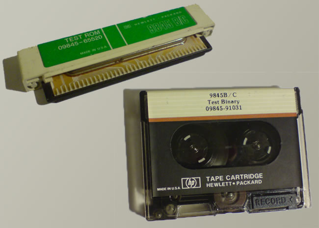
Test ROM and Test Binary Cartridge
HP's Test ROM for the 9845 is a wonderful tool for performing diagnostics on a 9845 system. It allows failure analysis even when many of the system components fail, which normally would prevent all other types of diagnostics like using the exerciser tapes. The 9845 Test Binary on the other side completes the test suite by providing comprehensive tests on dedicated assemblies which can be performed once the system is basically operational. Once the BASIC language system is operational, BASIC programs may be used to cover special tests which are easier to maintain.
Diagnostics and repair with Test ROM and Test Binary is done in three steps:
- In the first step, the core system functionality (processors, RAM, tape drives) is tested with just the Test ROM. Any defect which is encountered by the Test ROM should be handled, so that core functionality is guaranteed when performing the second step - loading and running the Test Binary program.
- The Test Binary program provides all the additional checks for testing most of the other system components, which have not yet been tested by the Test ROM. Once the system has been booted with the Test ROM, the Test Binary will automatically be loaded for execution if either the AUTO ST key is latched or one of the tests provided by the Test Binary has been selected by the service engineer with one of the special function keys associated with those tests.
- Test ROM and Test Binary program cover mainframe diagnostics only. They are amended by the system exerciser tapes, which provide BASIC programs for more comprehensive testing on a higher level and also include firmware inspection and tests for numerous peripherals. So, the third and last step normally is to run the system exercisers.
Both the Test ROM and the Test Binary program are fully self-contained in the sense that no operating system is required for running the tests included. Therefore, both are written in assembler language and can be run without any system ROM involved. I have added some functionality to both the original Test ROM code and the original Test Binary code, which include remote operation from a PC via HP-IB if neither the 9845 keyboard nor the CRT is working, and also implemented a command shell for the Test Binary program.
The 9845 Test ROM
For understanding how the Test ROM works, here is a brief explanation. After power-up, all 9845 processors perform the same steps for initialization. Once the processor's clock is stable, it first checks at memory block 37 (octal 45) whether there is a ROM installed. If yes, the 9845 starts execution in this memory block at address 32 (octal 40). If no ROM is found at block 37 (which normally is the case), control is transferred to the instruction at address 33 (octal 41) of the ROM found at block 5, where the PPU system ROM ist situated.
Now it may happen that the system ROMs fail, maybe because wrong versions have been installed, or maybe because the ROMs are defective. Also bad RAM may prevent a successful boot process. In any case, if the system cannot boot up successfully, there is no way to load any diagnostics tools for isolating the fault.
Now the 9845 Test ROM is a pluggable option ROM which can be installed in the PPU ROM drawer. Its address logic is wired to respond to block 37, so once installed, both 9845 processors execute the Test ROM code at address 32 (octal 40) before they jump to the system ROM code in block 5.
The 9845 Test ROM code contains a small operating system kernel with all necessary I/O routines, and a test suite for performing analysis on exactly those components, which may - if being defective - prevent loading further diagnostics software for more general troubleshooting. So in particular the Test ROM includes diagnostics for the processors themselves, for the bus system, for system RAM and for the tape subsystem. Consequently, for every 9845 system which does not boot up successfully, using this Test ROM is the first choice to identify and replace the faulty component.
Unfortunately, the 9845 Test ROM is an extremely rare item. Although once part of the standard service equipment, it seems that most Test ROM packages have been disposed when support for the 9845 series was discontinued. However, fortunately there is at least one 9845B/C Test ROM existing, which is part of the HP Museum's collection. So it had been already possible in 2009 to read out the Test ROM code and make it available on this site.
Now the problem is that there is still a proper medium missing to make the ROM code accessable for the 9845 system. Building a home-made option ROM ist not that easy (although in principle achievable, the SSS Mass Storage ROM shows a way how to build an option ROM with two EPROMs and one PROM). In any case you need to design your own PCB layout since the ROM drawer requires an unusual contact raster.
Much easier is using an existing hardware setup: the 9845 ROM board replacement. In principle, you simply need to transfer the Test ROM code to the flash memory of the ROM board and then boot the system with it (see the ROMboard Project Section for more information on this). Since the ROM board is to be used as piggy back with an existing A27 or A28 RAM/ROM assembly which can be assigned to ROM blocks 3 or 5, but not to block 37, the Test ROM code has to be adjusted to work in block 5 (the PPU system ROM block), which is automatically started if no ROM at block 37 is found.
Once this code relocation task was done, the modified Test ROM code simply had to be added as additional choice to the flash ROM package for the 9845 ROM board. With the right DIP switch setting, it then can be selected whether the system shall boot from the normal system ROM, or, if this fails, from the Test ROM for some deeper diagnostics.
The drawback of using the ROM board as a home for the Test ROM code is that - because the ROM board plugs in as replacement for the PPU ROM assembly - that assembly cannot be tested. This is especially true for the PPU ROMs. There are two workarounds. One is to verify the ROMs individually with an EPROM programmer (see the ROM dumping tutorial), the other is to replace the ROMs on the LPU ROM assembly with those of the PPU ROM assembly, and let the Test Binary program calculate checksums on them.
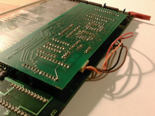
ROM Board Solution Mounted to an A27 (09845-66527) PPU RAM/ROM Board
HP's 9845 Test ROM has been designed as an 8K option ROM, so all code has to fit into 8,192 bytes. This includes start-up initialization and test routines, all necessary I/O routines, two test packages (one for for testing system RAM and one for examining tape operation) and a very basic user interface.
The initialization and startup test routines are executed after power-up and after each keyboard input of CONTROL-STOP.
Test ROM Menu Prompt (Remote View)
Start-Up Tests
With the Test ROM installed, the 9845 performes a couple of start-up tests after powering up or CONTROL-STOP. The tests include:
- PPU test (BPC binary processor, IOC I/O controller, EMC extended maths, AEC address extension & memory addressing)
- LPU test (same as above)
- Unique block test (no memory blocks responds to two block addresses)
- Memory block 0 (LPU system memory) read/write test at address octal 40 to 77777, performed for each address first with the LPU, then with the PPU
- Memory block 1 (PPU system memory) read/write test at address octal 40000 to 77777, performed for each address first with the LPU, then with the PPU
Memory Error During Start-Up Memory Test (Block 0, Remote View)
Those tests can be extremely important, because the most essential computer functions are verified. If your system has a startup problem, this is the most valuable test to identify the problem. If even this test won't start, you got a hardware problem which cannot be solved with test firmware only.
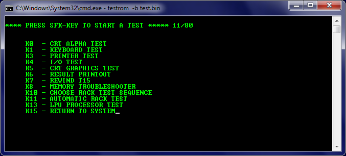
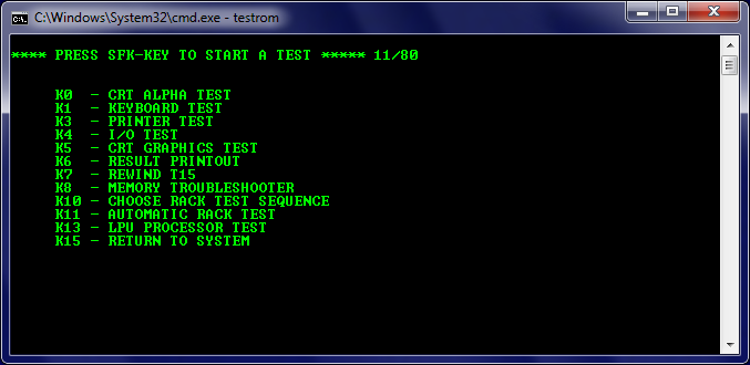
When all initial tests have passed, the message "**** PRESS SFK-KEY TO START A TEST *****" is shown, and you can either choose one of the built-in tests (executed with special function keys K2 and K9) or one of the Test Binary exercisers (all other special function keys).
K2 Tape Test
This test is run with the special function key K2.
You need a good blank tape cartridge for this test (data on the tape will be erased). The tests can be performed on both the standard (right-hand side) drive and optional (left-hand side) drive. When asked for the drive to be exercised, type S for standard and O for option drive.
For testing a tape drive you can choose between a self-running exerciser covering all tape functions, or dedicated tests for certain functions. Basically, the exerciser test performs a full rewind/initialize/write/verify/read sequence.
The automatic exerciser (select N when asked for selecting the test routine) runs the following steps:
- Rewind tape
- Initialize tape
- Write 16 records on tape
- Verify the records
- Read the records
Much can go wrong with the tape drives (sensors, logic, connectors, servo, magnetic read/write head, analog circuits, calibration etc.), so the exerciser test includes numerous individual checks. Thereby, the tests may cause the following errors (press CONT to continue testing after an error):
- Cartridge out switch
- Write protect switch
- Tachometer pulse failure
- Servo failure or hole error
- 9845A format
- No contact (electronics not connected)
- Tape not initialized
- Record not found
- Checksum error
- Verify error
Manual testing (select Y when asked for selecting the test routine) includes:
- Rewind a tape (R)
- Pattern write test (W)
- Read the tape continuously in both directions (C)
- Motor motion test (M)
- Turn-on test for cartridge drive control and logic circuits (T)
- Start the exerciser manually (E)
All tests can be stopped with the STOP key. Be careful with the motor motion test since it may unspool your tape.
You should examine both the Desktop Computer Service Manual for the HP 9845B/C (chapter 2) and the 9845B/C CE Service Handbook (chapter 5 "Mainframe Diagnostics") to get a full description of this test.
K9 Memory Test
This test is run with the special function key K9.
The K9 test is essentially the same as performed during start-up (marching pattern, refresh and byte tests), but on a selected memory block. You must enter the memory block to be tested from the numeric keypad in octal notation. Selection is restricted to even memory block numbers (so block 1 for example can not be selected). The memory test repeats until terminated with the STOP key. Selecting a non-existing block number will give an error message "BLK X NOT PRESENT".
Entering 100000 as block number performs tests on all even memory blocks.
Each memory error show the block number, the address where the error has occurred, the data which was read and the data which had been written before (which would have been expected). This information can be used to identify the defective assembly (by block number), whether the address decoder logic, the refresh logic or a DRAM chip causes the error, and for a chip failure which chip is defective and should be replaced.
This test does not check any ROMs. To verify ROM integrity, there is a ROM test included in the Test Binary's memory test.
See the Desktop Computer Service Manual for the HP 9845B/C (chapter 2) and the 9845B/C CE Service Handbook (chapter 5 "Mainframe Diagnostics") under "Memory Troubleshooting" on details on how to interpret the error messages.
The 9845 Test Binary
In principle, HP could have packed the whole test suite into one singe option ROM. However, there had been several disadvantages to include all those tests in ROM. First of all, firmware is generally less flexible than tapes in terms of updates. Introducing new test binaries on tape had been much easier than producing new option ROMs. Next, tape cartridges could be produced with less cost and even be re-used for other purposes if required. Finally, ROM space is limited to one memory block (which is the equivalent to 64 kBytes) whereas a single tape can hold up to 213 kBytes.
Whereas using a tape cartridge only for the full test suite would not have been possible (RAM, ROM or tape defects might prevent loading software from tape), it had been reasonable to place some core systems tests into the Test ROM, and non-core tests on tape. So the hybrid ROM/tape approach was born.
Loading the Test Binary
The 9845 Test Binary can be loaded from tape cartridge by the Test ROM (simply use other special function keys but K2 and K9), or during normal BASIC operation with the LOAD BIN command. Once loaded, the Test Binary takes full control of the system. This is possible, because the binary program itself holds all necessary routines for operating the complete system and does not call any firmware routines resident in ROM. As it is a binary program, all code is machine code written in assembly language.
Test Binary Program Main Menu (Remote View)
Main prerequisite for loading the Test Binary is that there is enough functional RAM available in block 0 (the LPU memory block), where the all the Test Binary code can be stored for execution (in contrast to the Test ROM, which in most cases uses the base page area only for variables and buffers). This also limits the maximum size of the Test Binary to 64 kBytes. Also there must be some working mechanism to transfer the binary program from the storage medium into RAM (normally via reading from tape).
Both can become a problem. If there is not enough functional RAM available, either working RAM has to be added (e.g. by installing some more system RAM) or the defective RAM chips on the assembly have to be identified and replaced. The Test ROM helps performing the latter, since it checks RAM and in detail reports which chip has to be replaced. If the tape subsystem is not operative, in principle the same applies. The Test ROM supports checking the tape functions so that repair efforts can be directed to the faulty components.
Test Procedures
The following test procedures are provided by the Test Binary program:
| Procedure | Description |
| K0 CRT Alpha Test | Checks all CRT alpha functions (alpha buffer, character sets, features, switching to graphics mode) and provides test patterns for adjusting focus and alpha raster size. |
| K1 Keyboard Test | Checks all keyboard keys including latches, modifiers and functions keys. |
| K3 Printer Test | Checks internal printer logic circuits and provides a printout to check for missing dots, print intensity and character alignment. |
| K4 I/O Test | Checks I/O lines (IC1, IC2, status and flag), I/O backplane, reading data to and reading data from an interface, DMA and interrupt functionality. Requires four general I/O interfaces (98032A) with test connectors installed. |
| K5 CRT Graphics Test | Checks the graphics memory with different patterns and all CRT graphics commands (cursor control, data reads & writes). |
| K8 Read/Write Memory Troubleshooter | Provides a number of specific memory tests (marching pattern, refresh, byte, walking bit) and a peek/poke functionality to manually read from or write to memory at a given block number and address. |
| K10 Rack Test | With this function you can define your own test suite. The following special tests can be combined in order to be run in the seuqnce defined by the user:
Note that the system ROM test and the T14 optional cartridge test can be run as part of a rack test only. Also note that the tests can be configured without CRT with the original (not modified) Test Binary - the configuration menu is printed on the internal printer. If a hardware option (graphics, cartidge drives, printer) is not installed, those tests are automatically skipped. |
| K11 Automatic Rack Test | This test is intended to continuously exercise the 9845 system. The same tests are included as with the K10 rack test, except that all tests are performed in a given sequence and in a continuous loop until STOP is pressed. The time consuming walking bit test within the memory test is only performed when the PRT ALL key is latched. If a hardware option (graphics, cartidge drives, printer) is not installed, those tests will be skipped. This test will be automatically started if the Test Binary program is loaded with AUTO ST key latched. |
| K12 Factory Test | ROM bit test. This test is intended for factory tests only and requires an extra tape cartridge with ROM data to compare to. This test is not listed in the Test Binary main menu. |
| K13 LPU Processor Test | Performs a comprehensive test of the LPU's registers and functions. |
Other Test Functions
Some more functions can be used to display recorded test results, rewind a tape or pass control back to the operation system:
| Function | Description |
| K6 Display Results | Prints a summary on all performed tests, including the number of runs and the results. Also gives an overview of the read/write memory installed (does not recognize memory block above block 16). By pressing STORE, the summary can be copied to the printer. |
| K7 Rewind T15 | Simply rewinds the cartridge in the standard T15 tape drive (same as with normal BASIC operation). |
| K15 Return to System | Performs a check on the system ROM and afterwards pass control back to the operation system. |
For details on all K0-K15 test functions, please refer to the Desktop Computer Service Manual for the HP 9845B/C (chapter 2) and the 9845B/C CE Service Handbook (chapter 5 "Mainframe Diagnostics").
Custom Changes to the Test ROM and the Test Binary
There are some restrictions on HP's original Test ROM and Test Binary which work out disadvantageous today. Main problem is that the Test ROM is an extremely rare item (only one single exemplar is known). Next, the Test ROM relies on a working keyboard and display, which however may be part of the problem. Finally, the Test ROM assumes a working tape catridge drive, which today is a challenge on its own. So I did a couple of changes on the original code.
As already mentioned above, I had to modify the original Test ROM code for execution in memory block 5 instead of memory block octal 45, so that the Test ROM code can be included into the ROM Board.
I also decided to add some functionality for the Test ROM to implement loading binaries from the HP-IB bus in addition to loading them from tape. This of course requires a functional HP-IB interface available, but those interfaces in general can be considerd as standard equipment (even more than the serial interface). Most systems had at least one of those interfaces, and if not, they are relatively easy to acquire even today (and you won't have much fun with those 9845 without it anyway).
As with other software from this site, the setup for loading binaries from the Test ROM includes a 98034A/B interface, and a standard PC equipped with a GPIB interface as source. And, of course, some program on the PC for feeding the data to the HP-IB bus. Loading binaries with this setup is not limited to the Test Binary, in fact any binary can be loaded into the 9845 RAM and automatically executed. This small extension of the Test ROM now provides a functionality which has never been part of the 9845 concept: To start with a small executive kernel in ROM, to automatically load all other operating system code into RAM, and then pass control to it. Which is also called bootstrapping.
Now in fact, for bootstrapping, the binary which shall be loaded has to be self-contained in terms that it includes all necessary routines for operation. One reason for not using the routines built into system firmware is, that the ROMs may be defective (which unfortunately is the case for estimated 80% of the 9845 computers today). The other reason is, that not all entry points for those routines have been cleanly positioned into version independent vector tables, so calling firmware routines may work with one system but not with the other. The number of binary programs, which bring their own operating system and can operate independently of the firmware, is limited. The Test Binary is one of them.
I have also modified the original Test ROM and Test Binary program code to include support for remote PC terminal operation (see 9845 Remote Operation section below). Furthermore, a simple command shell has been added to the Test Binary for running the tests and doing even more diagnostics (see the 9845 Test Console section below), which can be launched with the special function key K14.
Finally, I have added the printer log function to the Test ROM. You can activate it by simply latching the PRT ALL key. All CRT output is then sent also to the internal printer (if installed).
Please note that this modified TBIN Test Binary program can't be loaded and run with the LOAD BIN command within BASIC. Reason is that I have not yet implemented proper initialization code for this. Use the original (unmodified) TBIN version for LOAD BIN (see System Utilities section for this original version).
All sources for those modifications can be found in the Downloads section at the end of this page.
The 9845 Test ROM Binary Loader
The HP 9845 Test ROM does support tape cartridges for loading the 9845 Test Binary. As already mentioned above, no other mass storage type is supported, nor are there any functions to communicate with the outer world, e.g. for exchanging test data or driving remote printers.
Unfortunately the tape drive is one of those components, which suffer most from aging. Tape cartridges today are a quite unreliable storage medium, and the tape drives in most cases do not work due to gooey capstan rollers. In order to provide more reliable mechanism for loading software from the Test ROM, there must be some alternative.
The most flexible way is to use a standard PC as source for the Test Binary, for which some code has to be added to the 9845 Test ROM in order to retrieve the Test Binary e.g. via HP-IB instead from tape. Such an HP-IB connection would require both a 98034A/B HP-IB interface, and a GPIB board for your PC, plus some PC program to feed the Test Binary program towards the HP-IB bus.
The modifications I did for this in the Test ROM code are 'minimal invasive', in a way that the modified Test ROM still works 100% like the original, but offers some additional features. The changes come into action if the SHIFT LOCK or the AUTO ST keys are latched. Normally, the 9845 Test ROM automatically tries to load the Test Binary from tape when the user selects one of the tests which are implemented in the Test Binary, but not in the 9845 Test ROM. That means, all special function keys except K2 (tape drive test) and K9 (memory test) will start loading the Test Binary from tape. If there is no tape in the drive, the Test ROM shows a "CHECK CARTRIDGE-OUT SWITCH" message, and if a cartridge is loaded, but no Test Binary is on the tape, the message "TESTBINARY NOT PRESENT" is shown.
Now with the 9845 Test ROM extensions, if SHIFT LOCK is latched when a test is requested which is not part of the Test ROM, the modified Test ROM looks for an 98034A/B HP-IB interface installed with select code 7. If no HP-IB interface is found, "NO 98034 AT SELECT CODE 7" is displayed. Otherwise, the message "START REMOTE FILE SERVER AT ADDRESS 20 & PRESS <CONT>" is shown. With a proper HP-IB connection between the 9845 and a PC, some small utility program now can be started which should wait for being actively addressed to talk to the HP-IB bus and then for a trigger event. When the <CONT> key is pressed on the 9845, a trigger event is sent over the HP-IB bus, which is the signal for the PC transfer program to start sending the Test Binary program's data to the HP-IB bus.
With receiving the very first data block of a binary, the Test ROM already can check whether the ID of the binary is as expected (in case of the Test Binary program, the ID is "TBIN") and how much data is at least required to transfer the whole binary program. This applies both the loading the binary program from tape and via HP-IB. For the latter, it is good habit for the transfer program on the PC side to mark the very last byte with EOI asserted, but not required.
In SHIFT LOCK mode, the HP-IB transfer routine is a bit more relaxed than the tape load routine is. In particular, the HP-IB routine does not reject a binary if the ID is something else but "TBIN". However it must be a valid binary program, and has to carry an execution entry for passing execution to the binary program after the load is complete. If some error happens during transfer, or the data is not a valid binary program, a message "LOADING BINARY FAILED" is shown.
SHIFT LOCK can be combined with AUTO ST, with the effect that after all start-up tests are finished, the HP-IB loader routine is automatically launched and also does not wait for <CONT> to be pressed, assuming there is already a transfer utility at the PC waiting for being signalled to start the data transfer. If no data is being sent from the PC to the 9845, a "HP-IB TIMEOUT" massage is shown.
9845 Remote Operation
Using the Test ROM requires some operational core components. This includes the PSU and both processors, but also some minimum of read write memory for some base page variables, a functional mainboard, and both the alpha control assembly and the CRT. The keyboard is not required for performing the automatic start-up tests, but for selecting and configuring all other tests.
Now it can happen that even those minimum prerequisites are not met. So what if the alpha control, the CRT or the keyboard does not work? During the early 80's, a system engineer would have simply replaced those items. Today in most cases we need some more sophisticated handling.
It was not too far to think about adding some more functionality in the Test ROM for implementing remote operation, i.e. using a remote PCs keyboard and display to replace that of the HP 9845. Again the HP-IB seemed to be the right choice to attach such a remote terminal (normally the serial interface is used for such purpose, however, due to the fact that the HP-IB interfaces are much more common for the 9845, this again is the interface of choice).
So I checked the Test ROM code for where to add some own for remote operation, and believe it or not, I found that exactly the same idea obviously already inspired HP's Test ROM programmers, because there is some code included which obviously was meant exactly for utilizing the HP-IB for this purpose. Unfortunately it seems that the implementation of this function never had been finished completely. In fact I was not able to get it working. Also, the implementation required the 98034 HP-IB interface to be configured as non-system controller, which is not the default.
So I decided to add some code on my own, and implemented full terminal operation for the 9845 via HP-IB with both the Test ROM and the Test Binary. As a result, you now can test your 9845 also when keyboard, alpha control or CRT are non-operational, and since remote control works in parallel to the 9845's keyboard and CRT, you can see all PC keyboard inputs on the 9845 CRT, and all 9845 keyboard inputs on the PC's display respectively.
You even can operate the 9845 fully without keyboard or CRT, provided that you install a small PCB, the so-called Turn-on Fixture as substitution for the CRTs vertical retrace signal (see the appropriate section below). Note that - since I added the remote operation code only to the Test ROM and the Test Binary - remote operation is limited to those programs, and not available for normal 9845 operation (with BASIC and so on).
See section "The Test ROM Program" below for how to set up a remote connection.
Note that all screenshots on this page have been taken from the remote control window.
The 9845 Test Console
Both the 9845 Test ROM and the Test Binary are menu-driven, i.e. the user interaction does not include a command interpreter or command shell. This can be quite comfortable for testing, but is also restricted to testing. Or, in other words, there is some kind of kernel as operating system core, but it is not possible to use it for any other purpose since there is no way for the user to start programs, to work with files or whatever else would be common usage with a command interpreter.
So, when looking at the kernel routines which provide core keyboard and display functionality, I found it a worthwile challenge to add a command shell on my own. This also would be a nice practice for assembler programming on the 9845. I started with extending the Test Binary program, since compared to the Test ROM it is easier to debug. Changing ROM code even with flash ROMs is always a time consuming procedure, whereas a binary simply can be reloaded.
The result is what I call the 9845 Test Console program. It has been integrated in the Test Binary code and can be launched from the Test Binary main menu with special function key 14 (SFK14). This has been left unused by the Test Binary progammers and so is perfectly suited for this kind of extension.
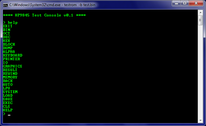
Once in the Test Console, you can work with a HP 9845 just like with DOS, a linux shell or a Windows command shell. There are currently 24 commands implemented. A command overview is listed using the HELP command:
Test Console (Remote View)
The commands include keywords for starting the individual test programs. Command input is case insensitive, so both upper and lower case input is allowed, even mixed case won't matter. I personally prefer lower case as default, but this finally is a matter of taste. All input is done at the prompt with the blinking cursor.
The command shell can be terminated with the STOP key or the EXIT command, the system then goes back to the test menu. The SYSTEM command passes control back to the system ROM (if installed).
In addition to the commands for starting the individual test programs from the command prompt (ALPHA, KEYBOARD, PRINTER, IO, GRAPHICS, MEMORY, RACK, AUTO and LPU) there are some useful utilities for showing test result overview, rewinding the tape, as well as for number conversion, memory dumps, clearing the screen, executing programs or saving/loading memory content via HP-IB.
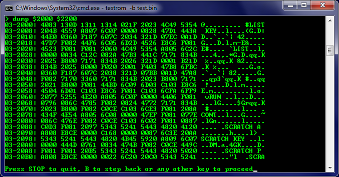
Sample Memory Dump of LPU ROM Block 3 (Remote View)
Numbers (as used for addresses etc.) can be used interchangeable with decimal, octal, hexadecimal or even binary representation. Octal numbers are identified with trailing 'B', hexadecimal numbers are preceeded by a leading '$' and binary numbers with a leading '%'. Examples are:
12345 is a valid decimal number, as well as -12345
100B is an octal number with decimal value 64
$ffff is an hexadecimal number with decimal value -1
%1000 is a binary number with decimal value 8
All numbers represent 16-bit values. Decimal numbers can be used within the range of -32768 to 32767, octal numbers within 0B to 177777B, hexadecimal numbers within $0 to $ffff, and binary numbers within %0 and %1111111111111111. All other values lead to an illegal value error.
The command syntax is shown in the following overview:
| Command Syntax | Purpose / Description |
| exit | Leaves the test console and re-enters the main menu. |
| bin [<number>] | If entered with <number>, converts <number> to its binary representation. Sets binary output mode if entered without parameter. |
| oct [<number>] | If entered with <number>, converts <number> to its octal representation. Sets octal output mode if entered without parameter. |
| dec [<number>] | If entered with <number>, converts <number> to its decimal representation. Sets decimal output mode if entered without parameter. |
| hex [<number>] | If entered with <number>, converts <number> to its hexadecimal representation. Sets hexadecimal output mode if entered without parameter. |
| block [<blocknumber>] | Sets current working memory block to <blocknumber> or prints current memory block when used without parameter |
| dump <start> [<end>] | Outputs memory dump using the current output mode (octal, decimal, hexadecimal or binary) covering the memory area from <start> to <end> (inclusive). <end> can be omitted for single memory address data. Default output mode is hexadecimal (includes ASCII). |
| alpha | Run the CRT alpha test |
| keyboard | Run the keyboard test |
| printer | Run the printer test |
| io | Run the I/O test |
| graphics | Run the CRT graphics test |
| result | Show test results |
| rewind | Rewind T15 (standard right hand tape cartridge) |
| memory | Run memory troubleshooter |
| rack | Run rack test |
| auto | Run automatic rack test |
| lpu | Run LPU test |
| system | Pass control back to the system ROM (if installed) |
| load <address> | Load memory in the current working memory block starting at <address> with data from HP-IB (must be terminated with EOI). Type Alt + L on the PC side when using the Testrom program for uploading data before starting this command. |
| save <start> <end> | Save memory content from the current working memory block from <start> to <end> (inclusive) to HP-IB with EOI on the last byte. Type Alt + S on the PC side when using the Testrom program for downloading data before starting this command. |
| exec <address> | Execute program at <address> in the current working memory block. The program must terminate with RET 1 to return to the command shell. |
| cls | Clear console screen. |
| help | Print an overview of the available commands. |
A detailed description of all test programs can be found in chapter 2 of the the Desktop Computer Service Manual for the HP 9845B/C.
Note on test programs: Not all test programs return to the command shell after finishing, some directly jump to the main test menu.
Memory address note: All memory refrences in the DUMP, LOAD and SAVE commands apply to a single memory block only (the current working memory block which can be selected with the BLOCK command). Since each block covers exactly 64 kBytes or 32 kWords, the address range is limited from 0 to 32767. Higher address values will be automatically mapped to this range. The EXEC command behaves the same, except that addresses above 32767 will not be mapped to the working memory block, but rather be used as reference in the same block where the Test Binary resides. The program which is launched by the EXEC command with an execution address of below 32768 should be aware that its instruction space is mapped to the lower address range. It is good habit anyway for a program to check for its current address via program pointer on program launch, since the LOAD command does not adjust any vector tables like the BASIC LOAD BIN command does.
HP-IB note: LOAD and SAVE operations assume remote data source / sink in device mode at HP-IB address 20. The remote data source must wait for being addressed to talk before sending data, the remote data sink must wait for being addressed to listen before receiving data. All data transfers must be terminated with EOI asserted on the last byte.
Testrom program note: Currently, neither the LOAD nor the SAVE command can be issued from the Testrom program on the PC side if operating as remote console, since the Testrom program has to be set to transfer mode before LOAD or SAVE is entered on the 9845.
The Turn-on Fixture
Normally, the 9845 can't be operated without a CRT monitor attached. The only technical reason for this is that a special periodical signal, the vertical retrace, is generated in the CRT circuits, and connected via the monitor legs to the mainframe and there to the HLT input of the PPU on the 9845B/C (or to the DC input of the PPU on the 9845A). Since there is no connection to the LPU, and the signal repeats every 1/60 second, each processor simply waits for a short time for the vertical retrace signal, and identifies itself as the PPU (if detected) and as the LPU (if not detected).
Also, another line (CRT) must be grounded in the CRT circuits in order to recognize for the processors that a monitor is installed.
If any of the two conditions (vertical retrace and grounding the CRT line) fail, the system firmware stops completing the start-up process. Unfortunately, this is also true with the Test ROM. The Test ROM then gives a message "HALT LINE NOT WORKING" to the screen, whether it installed or not. The normal system firmware gives a warning in terms of continuous beeps.
Now with a printer installed, there is not necessarily the need to use the CRT as output medium. Even more, if using the remote control function described on this page, a non-working CRT can become a serious problem.
It seems that for HP this had been a similar handicap, so the engineers quickly developed a small PCB they called "turn-on fixture" (part no. 09845-66547), which apparantly allowed powering up and using a 9845 system with CRT detached. This small device is mentioned in the later versions of the service manual on page 2-3, where also a short instruction is included how to use this fixture. It can be used both with the Test ROM installed or with a normal system setup (system ROM with BASIC). Once started with this small device, you can guide all output to the printer (latch PRT ALL for the Test ROM or enter 'PRINTER IS 0' for BASIC).
Since in principle it is obvious what the Turn-on Fixture does, I simply created a home-brewed prototype, which - surprise - really does the job. I used an NE555 (one of the absolute classics) for generating the vertical retrace, and included some diagnostic LEDs to quick check the voltages provided by the mainframe to the CRT.
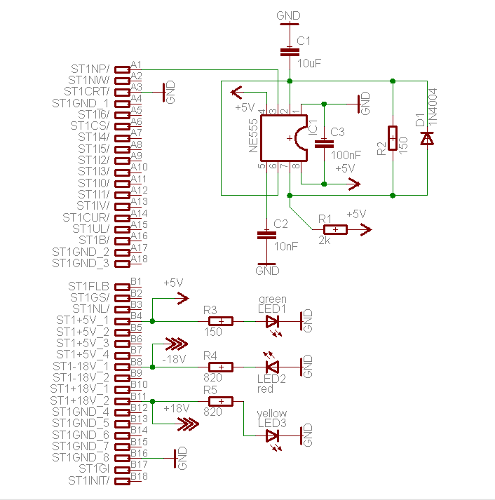
9845 Turn-on Fixture Schematics (Eagle, Click to Enlarge)
Note that in the above schematics, the +5V, -18V and +18V voltages are supplied by the mainframe connector and are included for the Eagle auto router only.
The NE555 works as astable multivibrator and is tuned by the R1, R2 and C1 to produce a 62.73 Hz signal with 1 ms low, which is pretty close to the nominal 60 Hz produced by the real CRT.
The original design of the turn-on fixture included a green LED as operation indicator, I have added two more LEDs so that you can check whether all three voltages supplied from the mainframe to the CRT are present. If you like you can either prototype the board as I did, or you can use the Eagle data for the sample board layout to let a PCB shop create the board for you.
Here is what you need for the board:
IC1: NE555
C1: 10 µF
C2: 10 nF
C3: 100 nF (decoupling capacitor)
R1: 2 kOhms
R2, R3: 150 Ohms
R4, R5: 820 Ohms
One diode and three LEDs (green, red, yellow)
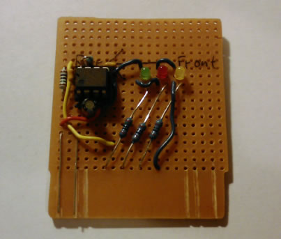
Turn-on Fixture Prototype
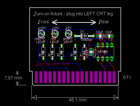
Turn-on Fixture 2-Layer Sample Board Layout
Please note that the above board layout is just for your convenience and has not yet been tested.
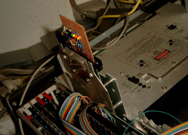
Turn-On Fixture Prototype Mounted on Left CRT Leg (with analyzer connected to PPU)
The Testrom Program
For the custom changes to Test ROM and Test Binary which use HP-IB connection, there has to be a program on the PC side to serve the connection.
This program takes all the data from the remote 9845 system over the HP-IB to reproduce the display on the PC, and - vice versa - send keystrokes from the PC keyboard back to the 9845 system. The program also serves as a source for transferring files to the 9845 (e.g. for bootstrapping or loading the Test Binary program via HP-IB). This is what I have written the Testrom program for. It uses a Windows console as terminal environment, and interacts with the 9845 via a simple I/O protocol over the HP-IB connection.
Prerequisites
You need
- a 9845 with at least core assemblies operational (PSU, processors, mainboard, I/O backplane and a minimum of system RAM),
- a ROM board from the ROM board Project with a flash programmer,
- an HP-IB interface (revised 98034A or 98034B),
- a GPIB interface for the PC (all interfaces which work with HPDir are supported, see the HPDir Section for details), and
- a PC with any type of Windows (NT/2000/XP/Vista/Win7 need a portio driver if an ISA GPIB board is installed).
Load the ROM board with the firmware containing the custom 9845 Test ROM (see download section at the end of this page) and connect 9845 with an PC with the HP-IB/GPIB interfaces. If required, configure the 98034 HP-IB interface as system controller (this is the default, any address except 20 is allowed) and the GPIB board as device.
Getting started
The easiest way to work with the Testrom program is to open a console window, and run
testrom
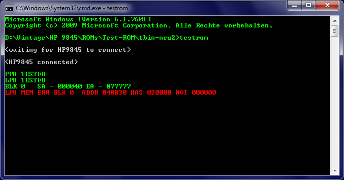
The program then outputs the message "<waiting for HP9845 to connect>" and starts listening under the GPIB address 20 for the 9845. Once the 9845 is connected via HP-IB to the PC, the modified Test ROM is installed, and the 9845 is powered up or CONTROL-STOP is pressed, the 9845 tries to communicate with the PC Testrom program. If both are connected, the message "<HP9845 connected>" is printed, and the Testrom program starts capturing the 9845 output.
This should result in the start-up test output like this:
PPU TESTED
LPU TESTED
BLK 0 SA - 000040 EA - 077777
When the start-up tests have been completed, the message "**** PRESS SFK-KEY TO START A TEST *****" is displayed, and the 9845 is waiting for input.
You have now the choice to either run one of the integrated tests with the F2 or the F9 keys, or to load the Test Binary for doing some more testing.
Type
testrom -help
for some more options.
If you need to log all output, you can either enable logging on the internal 9845 printer with latching the PRT ALL key (remote with Ctrl + Home), or you can suppress clearing screen with the -t option. Logging on the internal printer is currently implemented in the Test Binary only.
In principle, you can change the GPIB address where the PC Testrom program is listening with the -a option, however don't forget that both the modified Test ROM and Test Binary program expect the Testrom program at address 20, which is the default.
Loading the Test Binary Program from the Testrom Program
You now can load the Test Binary program either from tape or via HP-IB.
If you want to use a tape, simply insert a tape holding the Test Binary program, and select one of the tests with the appropriate function key. Note that the original Test Binary does not include the modifications which are necessary for remote operation, so this gets lost as soon as the original Test Binary has been loaded.
If you want to load the Test Binary program via HP-IB, you first have to latch the SHIFT LOCK key on the 9845. You can do this locally on the 9845, or remote with the PC keyboard. The Testrom program then asks you for naming the file you want to send to the 9845 (if you have used shift lock from the PC keyboard, it is now a good idea to unlock it). If the file has been found, you get a message the evreythin is ready for transfer and transmission starts when the Enter key on the PC keyboard or the <CONT> key on the 9845 keyboard is being pressed.
If everything goes well, the Test Binary program is startet and you get the following menu:
Test Binary Menu (Remote View)
Now you can start using those test programs from remote. Note that there is a hidden factory test which can be activated with K12, however it requires an extra tape cartridge which is not available. You also can enter the Test Console with K14 in case you have loaded the custom version of the Test Binary program..
9845 Bootstrapping with the Testrom Program
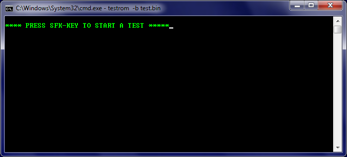
As mentioned in the earlier sections above, it is possible to use the modified Test ROM as loader for bootstrapping. This can be achieved in two ways: Either you are latching the SHIFT LOCK and the AUTO ST keys on the 9845 and use some transfer program like Sendfile (see the 9845 Utilities section), or you start the Testrom program as remote boot supervisor with the -b option.
When acting as boot supervisor, once the 9845 has been powered up and connected, the Testrom program directs the 9845 to perform an automatic boot process. Supposed that the boot binary program is in test.bin, you can do this with
testrom -b test.bin
Once the 9845 has connected and the start-up tests have been finished, test.bin is automatically transferred to the 9845 and executed. if you don't want to let the start-up tests run through, you can hit the <STOP> key on the 9845 or Esc on the PC keyboard at any time and the boot process gets shortened.
In fact the boot loader can be used to load and execute any kind of machine language program on power-up, as long as it complies to the 9845 binary program convention (i.e. is equipped with the appropriate binary program header with information on the size of the program and the vector on the address of the execution routine).
So in principle the boot loader provides what we used to know from many other systems which are designed with bootstrapping, such as the modern PC, and it can be used to load alternative operating systems on power-up either from the integrated tape cartridges or via HP-IB from a PC (who likes to port Linux to a 9845?). Loading from external floppy or hard disk drives is not yet supported (the required AMIGO or CS/80 mass storage protocol is not implemented in the Test ROM).
Screen Output
All screen output which is received from the 9845 system is mapped to the Windows console. Some restrictions on the Windows console functions make it less 100% accurate, since for example there are no attributes for blinking or underline. However looking at it from an overall view, it works pretty good.
Note that if the 9845 does direct writes into the CRT buffer, like during the Alpha CRT tests, those outputs will not be captured and displayed in the console window. But remember, it is the 9845 CRT which shall be tested during those tests, not the terminal connection. Same applies, of course, to all graphics output.
The Windows console cannot display inverse, blinking or underlined text. Alternatively, text attributes from the 9845 will be mostly color coded in the Windows console as follows:
Normal text (standard output): green
Inverse text (mostly error messages): red
Blinking text (progress): turqoise
Underlined text: magenta
Messages from the Testrom program itself will be in plain white and so can easily be distinguished from the 9845 output.
Keyboard Operation
All alphanumeric and symbol keys are being mapped appropriately from the 9845 to the PC's equivalents. Mapping for all other keys is shown in the following table:
| 9845 | PC | 9845 | PC | 9845 | PC | ||
| TAB SET | Shift + Tab | ↑ | ↑ | RUN | Shift + Page Down | ||
| TAB CLEAR | Ctrl + Tab | ↓ | ↓ | PAUSE | Shift + Esc | ||
| TYPWTR | Ctrl + Ins | ← | ← | CONT | Enter | ||
| SPACE DEP | Ctrl + Del* | → | → | CLEAR LINE | Ctrl + Num 7, Shift + End | ||
| STEP | Ctrl + Page Down | k1-k12 | F1-F12 | RESULT | Ctrl + Num 4 | ||
| DEL LN | Shift + Del | k13 | Shift + F10 | EXECUTE | Num Enter, Shift + Enter | ||
| INS LN | Shift + Ins | k14 | Shift + F11 | NUM E | Ctrl + Num / | ||
| PRT ALL | Ctrl + Home (toggle) | k15 | Shift + F12 | NUM ( | Ctrl + Num 8 | ||
| RECALL | Shift + Page Up | TAB | Tab | NUM ) | Ctrl + Num 9 | ||
| DEL CHR | Del | CONTROL | Ctrl | NUM ^ | Ctrl + Num - | ||
| INS CHR | Ins | SHIFT LOCK | Shift Lock | NUM = | Ctrl + Num 1 | ||
| AUTO ST | Ctrl + End (toggle) | SHIFT | Shift | NUM / | Num / | ||
| CLEAR | Shift + Home | BACKSPACE | Backspace | NUM * | Num * | ||
| CLR→END | End | STORE | Ctrl + Enter | NUM - | Num - | ||
| HOME | Home | REPEAT | n/a** | NUM + | Num + | ||
| ROLL UP | Page Up | STOP | Esc | NUM . | Num . | ||
| ROLL DOWN | Page Down | RESET | n/a** | NUM , | Ctrl + Num . | ||
| NUM 0 - NUM 9 | Num 0 - Num 9 | ||||||
Notes:
*) SPACE DEP is not actually a key but activated with CONTROL-TYPWTR on the 9845 side. However since TYPWTR is already mapped to a combination of Ctrl + Ins, the SPACE DEP function will be re-mapped to Ctrl + Del, which then sends CONTROL-TYPWTR to the 9845.
**) The combination of CONTROL-STOP on the 9845 is implemented in hardware and can't be triggered in software, so Ctrl + Esc on the PC would not initiate a soft reset on the 9845. Same applies to the REPEAT key.
Since there are no keys to be latched on the PC keyboard, this behavior is simulated for the PRT ALL and the AUTO ST keys by toggling the current state with Ctrl + Home and Ctrl + End keys. When toggling, the Testrom program gives a short message which state is currently active.
For using the PC's numeric keypad, the Num Lock key on the PC must be active (Num Lock LED must be lit). The Print and Pause keys keep their normal local behavior and are not used within remote control.
All specifications apply to international (US) keyboard layout both on the 9845 and on the PC side. There is currently no support for country specific characters (such as the § symbol). Mapping for non-US PC keyboards is widely achieved by using hardware independent virtual keycodes, however since the virtual key concept in Windows has its limits concerning symbol keys, this applies for the mapping in the Testrom program, too. I am personally using a German PC keyboard layout, so this is the only non-US keyboard which is currently fully supported.
Some special key combinations are defined for control actions on the PC keyboard:
| Alt + S | Set the Testrom client temporarily into receive mode (for saving data from the 9845 into a file) |
| Alt + L | Set the Testrom client temporarily into send mode (for loading data from a file to the 9845) |
| Scroll Lock | Disable sending all output from the 9845 to the remote client |
| Scroll Unlock | Enable sending all output from the 9845 to the remote client |
Receive mode and send mode are intended to work in combination with the SAVE and LOAD commands in the Test Console. Those commands can be used to transfer data from selected RAM areas to a file on the PC, e.g. for later inspection, or for loading data into selected RAM areas from a file on the PC, e.g. for executing code on the 9845.
Sending CRT output from the 9845 to the PC will be automatically disabled during data transfers (e.g. for sending boot code to the 9845 or during load and save operations) and re-enabled afterwards.
Downloads
Click here for downloading alle items referenced in this tutorial:
| Flash ROM Package with the modified 9845 Test ROM code included: | 9845-ROMBoard-Imageset.zip |
| Modified 9845 Test Binary Program (as hpi image file): | tbin-custom-10-hpi.zip |
| Testrom application (remote terminal client) for all Windows versions: | testrom-10.zip |
| Assembler Source Code for both the Test ROM and Test Binary Program Modifications: | test-mods-src-10.zip |
| Turn-on Fixture schematics & PCB layout (Eagle & CAM data, untested): | Turn-on-Fixture-Eagle-Data-10.zip |
These first versions may still have bugs. It is recommended to make copies from valuable data you are working on in case something goes wrong. Please use the contact feature to let me know if something doesn't work as expected.
More Information
Everything you need to know about the 9845 Test Suite, including the 9845 Test ROM and the Test Binary program, can be found in the Desktop Computer Service Manual for the HP 9845B/C (chapter 2) and the 9845B/C CE Service Handbook (chapter 5 "Mainframe Diagnostics") which both can be downloaded at hpmusem.net.
See the ROM Board Project for the hardware base to get the 9845 Test ROM working in your 9845B/C. Also see the 9845 Assembler Project for getting the tools necessary for programming the extensions.