The Fdio Project
Why and how
It is hard to imagine, but there was a time before the IBM PC. And even in the early years of the PC, by far not every system immediately adapted to the IBM standards. In fact, most vintage systems defined their own standards, so the early days of computing were determined by a much higher degree of heterogenity, than it is today.
One important objective of standards is to ensure interoperability, and interoperability between computer systems generally means using the same media, the same information structure, and the same semantics. In the era of the HP 9845, the floppy disk already was the most important medium for data interchange on desktop level, and some smaller computer systems even used floppy disks as standard mass storage, e.g. to load operating systems during system boot. Paper tapes and cards had their best times already behind them, and the mini tape cartridge was an indeed low cost alternative for local mass storage, but not really designed for interoperability with other systems. Fortunately, the floppy disk already had been standardized in form factor and magnetic characteristics, so from 3.5" up to 8" floppies the medium could be used in each floppy drive, provided that the form factor of medium and drive was the same.
Yet the information structure was not standardized at all. There had been industry standards like the IBM 8" format, but in principle, even the low level structure of tracks and sectors wasn't the same for all products. In addition, head count, cylinder count, sector count and sector size differed from system to system, which makes it sometimes really hard to gain access to vintage media on a modern standard PC.
Nevertheless, assumed you do own a PC with a floppy drive of the right form factor, there is in principle a good chance that the drive may read (and sometimes even write) those vintage media. Consider that a normal drive isn't much more than a spindle motor, a movable read/write head and some electronics to encode and decode the signals from the magnetic head to/from digital bits, even a modern floppy disk drive is theoretically capable of accessing the information stored on old floppy disks. Provided you tell the drive in detail what to do.
Exactly this is the problem with DOS, Windows and even Linux. There is a defined set of supported recording formats, and everything else will overburden the standard OS floppy drivers. The solution is on-hand, the floppy controller has to be programmed directly without the support of the OS drivers. This is exactly what the Fdio program does, it talks directly to the standard PC floppy controllers and tells them what to do in order to read or write vintage floppy disks.
I could have implemented yet another (alternative) Windows floppy driver, but due to the complexity of this approach I chose to simply develop a console program which does the job. Since direct device access without a driver is somewhat tricky under NT based Windows versions, I decided to use a special low-level controller driver developed by Simon Owen for this task. The FDRAWCMD package is a real good thing, and it is freely available.
Although handling 9845 and LIF floppies was the main reason to develop Fdio, its use is by far not limited to those formats. Fdio is quite generic, supports both FM and MFM encoding, and can be tuned for almost everything which can be handled physically by a standard floppy disk drive. However, not every standard floppy disk drive is physically able to read everything. And not every floppy controller is capable to process every disk format written by other controllers. Sometimes the tolerances are different, and either the error rates get high or the drive can't synchronize to the medium at all. In such cases, the only solution might be to connect a good old single density floppy disk drive, or even to use the original vintage drives and find another way how to transfer the data to and from a PC. However, with old used floppy hardware, also dirt, wear and aging may produce problems.
Is it Disk or Disc?
Well, there is a lot of use of both spellings, however, in general it is common sense to differentiate the digital from the analog world in that we use 'disk' for the use with computers, and 'disc' for all others, including audio use, even if the encoding itself is digital (e.g. compact disc).
The Floppy Disk
The floppy disk was originally developed as IBM 23FD at IBM for their System/370 mainframes and introduced in 1971. This original floppy disk had 8" (200 mm) diameter, could hold 80 kBytes of data, and was read-only (initial use was to store the system's microcode on the floppy which was loaded once from disk into memory during system boot). At that time, Alan Shugart had been Direct Access Storage Product Manager at IBM and was responsible for the development of the new media. From then, he got closely related to the later history of floppy disk and hard disk development.
In 1972, Shugart moved to Memorex where he and his team developed the first read/write floppy disk drive, the Memorex 650, now with 175 kBytes capacity. Just one year later, his former employer IBM shipped its first 8" read/write floppy disk drive as IBM 33FD for the IBM 3740 Data Entry System with about 250 kBytes stored within 77 tracks and 26 sectors per track of 128 bytes each and on one single side of the disk. That 3740 single-sided, single-density (SSSD) floppy disk format quickly became industry standard for data interchange among many computer systems even beyond the IBM world.
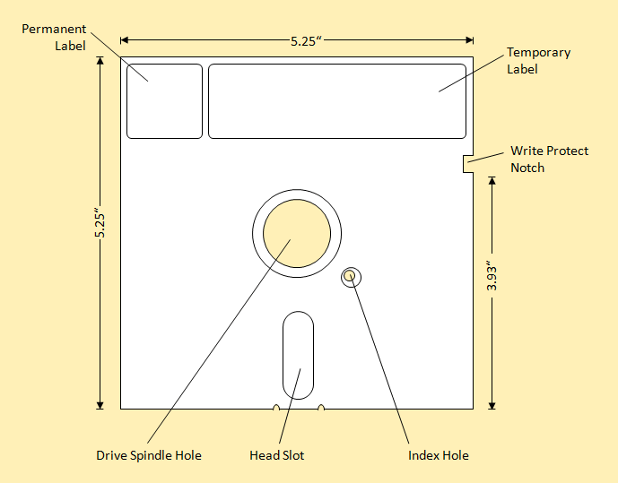
Floppy Disk Specs (5.25" Form Factor)
At that time, Alan Shugart founded his own company Shugart Associates, who developed the Shugart SA900, and later the SA800, which again became industry standard for 8" floppy drives. The SA800 and SA900 were (of course) capable of reading and writing the 3740 format, and the SA800 also doubled the possible capacity by using a modified frequency modulation (MFM) to about 500 kBytes (still single sided, but double density = SSDD). Later Shugart released the small brother of the SA800, the SA400 drive, with 5.25" form factor (single-sided, single-density) and the dual-sided version of the SA800, the SA850. The 50-pin controller interface of the SA800 became standard for most 8" floppy drives, and with some modifications (and reduced to 34 pins) also for later 5.25" and 3.5" drives.
Actually, the standard floppy interface used within the IBM PC is (almost) identical the 34-pin so-called Shugart bus, however there are minor deviations (see hardware section below). At NCC in summer of 1981 Sony introduced the 3.5" floppy disk, which encapsulated the way smaller floppy disk in a rigid plastic jacked which provided better protection to the disk. A metal slider covered the cutout for the read/write head, and a new metal centering mechanism allowed for much greater centering accuracy and thereby higher capacities. The motor spins with 600 RPM (which is twice the speed of a 5.25" floppy disk drive), which also increases the maximum possible transfer rate.
The 3.5" floppy first came with about 360 kBytes on a single sided double density (SSDD) disk, then doubled the capacity to the 720 kBytes on two sides (DSDD), and finally reached 1.44 MBytes with high density recording (HD), which still is the most common floppy disk type today. Also a high density variant of the 5.25" floppy disk with 1.2 MBytes capacity was introduced by IBM in 1984 with their AT PC, which quickly became standard for the 5.25" form factor. The 2.88 MBytes 3.5" extra high density (ED) floppy was pioneered in 1988 by Toshiba, but was never really accepted. Later different attemps were made to develop and introduce new substitutes for the floppy disk with much higher capacity, but none of those were successful in the end. Until flash memory sticks ruled the scene with reliable capacities no one ever thought about before.
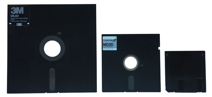
Floppy Types, 8", 5.25" and 3.5" Form Factor (left to right)
Besides the most common 8", 5.25" and 3.5" there had been several other form factors such as 2" or 3", but which never made it seriously into the market. Many computer manufacturers created their own floppy disk formats, which were not compatible to anything else.
HP actually joined the market in 1975 with their 9885 floppy disk drive. The 9885 used an 8" single sided double density (SSDD) disk and provided about 500 kBytes of storage on one disk. The drive featured a proprietary GPIO interface to the host. The "master" 9885M drive with its integrated controller could easily be extended by another, less complex 9885S "slave" drive. Later HP introduced the 9895A dual floppy disk drive, which featured up to 1,150 MBytes per 8" double sided double density (DSDD) floppy disk and 3740 backward compatibility. At the same time HP introduced the first 5.25" minifloppy drives, the 82901 and 82902, which provided 270 kBytes on a double sided double density (DSDD) floppy disk. The same floppy disk drive was installed in the 98x6/Series 200 desktop computers. The 9121 (SSDD, 270 kBytes) and 9122 (HD, 1.4 MBytes) represented 3.5" floppy drives from HP.
The floppy disk had many advantages compared to the existing magnetic media types of the time. Hard disks offered random access but were heavy and clumsy and - most of all - highly expensive for both drive and medium. Magnetic tapes on the other side ha a good cost per storage ratio, but were limited to strictly sequential data access. Magnetic storage cards were handy, but quite limited concerning their storage capacity. The new floppy disk combined low cost medium, random access and portability, which quickly made it first choice as mass storage for smaller computer systems. However, because of the direct contact between the read/write head and the medium, life time is limited (usually significantly below 200 hours of usage).
The floppy disk was built from a thin flexible piece of mylar coated with magnetic oxide. A plastic jacket should protect the surface against dirt and mechanical damage when being removed from the drive. A fabric layer - sometimes with Teflon - was used to minimize friction and to collect abrasion of the magnetic coating before it could spoil the read/write head. A cutout in the jacket permitted the read/write head to be in contact with the disk. Data was recorded in concentric tracks, in contrast to spiral recording of a vinyl platter. Each track was further divided into sectors, which typically held between 128 and 512 bytes of data each.
The data is actually encoded as magnetic flux reversals, which happen in a fixed timed sequence of so-called bit cells. Each bit cell represents the period, in which the read circuit expects the information for a single data bit. Depending on the encoding scheme, every bit cell consists of either two possible flux reversals (FM) or just one single flux reversal (MFM, M2FM etc.). It makes not much of a difference whether a flux reversal is changing from which polarity to the other, just the fact that there is a flux reversal (creating a peak in the read signal) matters.
For FM, there is always a flux reversal at the first half of the bit cell, which is used as clock bit signal to keep in sync with the medium, followed by a flux reversal or the absence of a flux reversal on the second half of the bit cell, denoting the value of the data bit. Which again represents the actual data being stored on the medium. If there is a flux reversal on the data bit, the actual data payload bit works out to 1, if there is no flux reversal on the data bit, the payload bit is 0. This technique, where the clock is recorded on the medium, is called self-clocking and makes read operations widely independent of minor changes in the rotation speed. A special circuit called data separator differentiates the payload bit from the clock bit, and so extracts the payload data bit from the bit cells.
Although easy to implement, requiring a flux transition for every bit cell just for the clock actually wastes lots of flux transitions. So more sophisticated encoding schemes such as MFM, M2FM and GRC (and also RLL for hard disks) were used, which had a better transitions per bit ratio, but also required more intelligent controllers. With more intelligent and less redundant encoding schemes, a higher data capacity can be achieved on the same maximum density of flux reversals (which is again a characteristic of the medium).
As a consequence, a single density floppy disk could double its capacity by simply using MFM instead of FM encoding, with the same physical characteristics of the medium. In fact there is no physical difference between floppy disk media labeled as single density vs. double density. Selling the floppy disk as double density could have been an indicator for being pre-formatted with MFM encoding, or for being manufactured with higher quality standards, but also could have been just a marketing trick to sell the same product for a higher price.
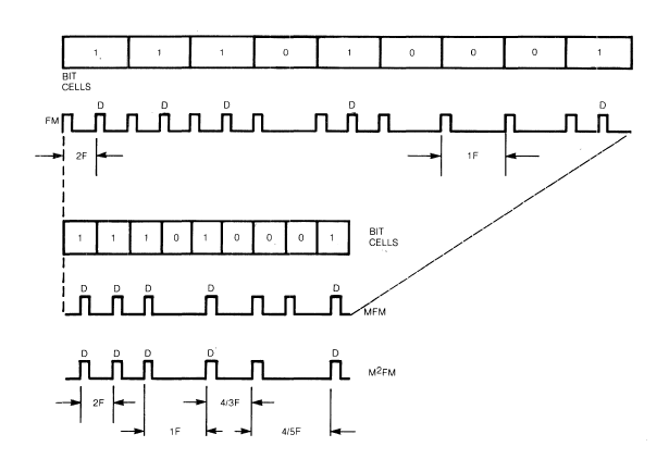
Comparison of FM, MFM and M2FM Encodings
There is an effect that transitions which are written closely together tend to appear shifted apart when they are read back. This effect is known as bit shift. The smaller the bit cells get, the more relevant this effect becomes. For a certain physical density, the writing circuit may put the flux reversals for certain bit combinations closer together to compensate for bit shift, sometimes only for the inner tracks where density is especially high. This technique is called precompensation.
The emulation of a HP 9895A dual floppy drives, which is part of the HP 9845 emulator (see the HP 9845 Emulator Project), by the way emulates floppy media on the level of flux reversals, which is pretty close to the physics.
All track data on an floppy disk is grouped into sectors, which consist of two main areas, an ID field and a data field. Each field, and each data field is made up of a defined number of bytes. Each field starts with a leading group of sync bytes, which is followed by an address mark and the sector ID (for ID fields) or the sector data (for data fields). All terminated by a CRC, which asserts integrity of the sector ID and the sector data, and sometimes followed by a postamble of additional sync bytes.
The ID field usually contains the current track number, the head number, the sector number, and sometimes the sector length. This allows sectors to be sorted interleaved on a track, which might be useful to achieve optimum access and data transfer performance. Bits which are not used for track, sector or head number can be used for something else (e.g. for flagging a sector as defective, also known as D-bit), The data field contains the actual payload data of each sector (sector data).
For IBM formats (including DOS formats) usually each track starts with a leading index area, after which the sectors are written. The index area starts with a leading group of sync bytes, which is followed by an address mark (the index address mark) without CRC. HP formats omit this index area and immediately start with the first sector.
There are several gaps which separate different areas in a track, usually with a defined number of zero or 0xff valued bytes. Gaps are required to write or replace individual areas without the need for rewriting the full track, allow the controller to do some processing of a sector after read before the next sector is reached, and also compensate for small deviations in rotational speed. Reducing gap lengths increases overall data capacity, but there are limits.
The first gap is the space between the rising edge of the index signal and the start of the index area (Index Gap, let's call it Gap 4a here). The next gap is the space between the index area and the first sector (Gap 1). Another gap (the ID Gap) is located between the ID field and the data field (Gap 2). Sectors do not seamlessly follow each other, but also are separated by a defined number of bytes following each data area (Gap 3, the Inter-sector Gap). Finally, there is a gap between the end of the last sector (including Gap 3) in a track and the next rising edge of the index signal (we call it Pre-index Gap or Gap 4b here), which may work out to be non byte aligned, because the appearance of the index signal immediately terminates writing this gap.
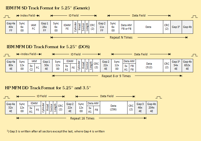
Some Example Track Formats
Inter-sector gaps (Gap 3) usually have two parameters, the length with which the gap is written during formatting, and the length which should be at least expected when reading or writing. This allows certain deviation when a floppy is formatted with one drive, and accessed with another, both deviating slightly in rotation speed. The access length is usually slightly shorter than the formatting length.
Address marks represents a certain pattern of clock and data bits, which usually is unique (i.e. cannot be created without violating the selected encoding scheme), so that those patterns can be utilized to sync within a stream of clock and data bits to the specific areas. Dedicated address marks are also used to mark certain tracks or sectors as reserved, invisible, defective or deleted.
This structure basically applies to all floppy formats. The formats, however, differ in the details. The whole format structure is normally only written to floppy disk once during the formatting process. After this, only the data fields including the CRCs get updated when writing data to the medium, all other information will stay unchanged.
Each format standard defines
- which kind of encoding is used (FM, MFM, M2FM, GRC etc.)
- which bit rate is used (depending on recording density and the rotation speed of the drive, which is usually fixed, but in some cases may change, e.g. for some Apple drives)
- how long the gaps are, and which byte pattern is used for writing the gaps,
- how long the sync byte areas are, and which byte pattern is used for the sync bytes (usually all zeros or FFs),
- which algorithm is being used for the CRC (usually CCITT standard),
- whether the preceeding address mark is included in the CRC calculation or not,
- which clock/data patterns are used for the ID and data address marks,
- whether the head number is included in the ID field or not (not necessarily required for single sided drives),
- whether the sector ID for the first sector starts with ID 0 or with ID 1,
- how many sectors fit in each track, and finally,
- how many data bytes are included in a sector data field (usually 128, 256 or 512).
Some copy protection schemes for floppy disks tweak those parameters in a way, that a protected program may prove the disk is an original disk, or even prevent standard copy tools from copying the floppy content. So copy tools like Copy II PC specialized on dublicating copy protected discs try to read and reproduce all of the above information, whereas the standard operating system drivers in general either ignore or try to correct any deviation from the standards. The copy software however has its limits where the disk was written in a non-standard way (e.g. with marginal writes, or intentionally false CRCs or other defects) which cannot be reproduced on a standard floppy disk controller. Here hardware tools like Catweasel, Central Point Deluxe Option Board, Kryoflux and SuperCard Pro which record the serial Data Out and write Data In lines of a floppy drive come into place for producing 1:1 copies.
Early media had been so-called hard sectored, which means they had tiny holes for indicating the position of each sector. Later this information was implemented with more flexibility as part of the magnetic recording (so-called soft-sectoring). On the other side, there were drives which didn't even utilize the index hole (such as some Ataris), writing information which cannot be read with many standard PC floppy disc controllers which have a 'blind spot' after the rising edge of the the index hole signal.
The original floppy disk had its magnetic coating only on one side, later floppy disks with recording capability on both sides were produced. In the early times, many floppy drives where single sided (i.e. had just one single magnetic head installed). At the time when dual sided media became available, many floppy disks manufacturers for cost reasons completely switched to the production of dual sided disks (thus avoiding two separate production lines), but still sold a portion of those officially as single sided. Clever users found out, that most disks could just be flipped to also take advantage of the second side (so saving costs for buying another disks). Now the drive has a sensor for the write-protect notch, so the jacket had to be cut out in order to enable write operation to the flipped disk. There were cheap punching devices available, also knwon as disk-doublers, to cut the square hole at the proper position.
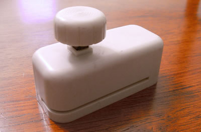
Write-protect Notch Puncher "Disk Doubler"
Obviously the inner tracks provide technically less capacity then the outer tracks, also due to the constant angle rotation speed inner tracks pass the read/write head with less speed then the outer tracks. However, for simplification, the inner tracks nominally hold the same number of sectors as the outer tracks, and therefore are more prone to errors then the outer tracks. It is not unusual that erroneous sectors aggregate primarily in the inner track area. As a consequence, valuable data such as directory data usually will be recorded in the outer tracks. Tracks are in general numbered from outer to inner tracks, so that normally inner track get less often used compared to outer tracks. As with hard disks, floppy disk sectors can be individually marked as defective, also some floppy disk formats are using spare tracks for replacing defective ones. However - once a floppy disks starts showing defects, it should be replaced.
Basically, the era of the floppy disk has passed. Only few PCs still offer built-in floppy disk drives. However, many systems still have a floppy controller on board, and of course floppy disks are still supported within any contemporary operating system. Most systems still have the ability built into the BIOS to boot from floppy disk, and external floppy disk drives can be attached via USB.
Besides, it is reported that parts or the U.S. nuclear missile arsenal still is controlled with 30 years old floppy disks (actually, with 8" form factor). No citation provided.
Floppy Disk Hardware
A typical floppy disk system consists of the medium (the floppy disk), the drive hardware (the drive mechanics with sensors and motor control plus some signal processing), the controller (floppy disk controller) and the driver running on the host system (the floppy disk driver). Any software (including the operating system itself) usually uses the floppy disk driver to access the data on the floppy disk. The driver is part of the operation system's driver stack and normally uses the I/O system to talk to the floppy disk controller. Communication between software and the driver is normally done via operating system (e.g. Win32 API) calls for high level (files) or low level (sectors) access, or directly by I/O control calls (IOCTLs).
The driver then uses a combination of reads and writes from/to the memory mapped registers of the floppy disk controller, as well as direct memory access (DMA) and hardware interrupts (IRQs), to interact with the floppy disk controller. The floppy disk controller is normally implemented around a single dedicated controller IC on the host's mainboard or a separate I/O card. This chip again is directly connected via a floppy disk cable to the floppy disk drive and directly controls the motor and sends or receives a serial bit stream to/from the floppy disk drive.
External floppy disk drives in general have their floppy disk controller together with the floppy disk drive in one housing, and the host connects to this device via some kind of standard interface, such as HP-IB, SCSI or USB, which needs a second controller for communication to the host.
The floppy disk drive basically consists of the spindle motor which lets the disk rotate at a constant speed between nominally 300 and 600 rotations per minute (RPM), and the read/write head with solenoid which senses the magnetic flux changes of the magnetic medium for reading, or creates magnetic flux changes on the medium for writing. Since the magnetic information is recorded in concentric circles (tracks), the read/write head is moved between those tracks with a stepper motor. There is some electronics for drive control, to amplify the signals, to translate between flux reversals and low level (clock & data) bit coding, and some additional mechanics to load/unload the medium. Finally there are sensors for detecting whether a medium is loaded (actually whether the drive's door is closed), whether it is write protected, whether the read/write head is at track 0 position and whether the index hole passes a certain position during rotation. Essentially, the floppy disk drive is not a too complex device.
Floppy disk drive characteristics include
- form factor (2" up to 8"),
- number of read/write heads (one or two),
- support for hard and soft sectoring,
- supported track density (48 up to 135 tracks per inch),
- supported recording densities (single/double or high density),
- rotation speed (300-600 RPM),
- timing (spin-up-time, head load/unload time, track-to-track seek time), and
- controller interface,
which all may differ among the different types and manufacturers. Floppy disk controllers range from solutions completely built from diskrete (e.g. TTL) logic over single-chip-controllers up to controller logic fully integrated into the mainboard chipsets.
Note that the floppy disk drive hardware stores data as flux transitions. The modulation type (FM, MFM, M2FM, GCR etc.) and related to this the interpretation of the bit stream (e.g. clock bit vs. data bit) is up to the controller. The modulation type has a strong influence on the effective capacity of the floppy disk and the effective read/write data rate. The low level data rate (bit stream) is basically a function of rotational speed and recording density. Typical data rates were 125 kBit/s (single density), 250 kBit/s or 300 kBit/s (double density), 500 kBit/s (high density) and 1 MBit/s (extra high density).
Since the floppy disk drive is a relatively dumb device, it can in general be tweaked to support many different floppy disk formats. Limiting characteristics are mainly the form factor and, for writing, the track width supported by the drive's read/write head. Also, modern floppy controllers in general support FM and MFM encoding, but not M2FM, GCR or even more exotic modulations. Some small computer systems such as Apple with its Disk II did most of the controller's work by the CPU for keeping hardware costs low. There had been a real industry specialized just on how to copy protect floppy disks, where limitations of common floppy controllers played an important role.
Floppy disk controller and floppy disk drive are usually connected via a 50-pin ribbon cable with edge connector for the older 8" floppy disk drives, and a 34-pin ribbon cable with either edge connector for 5.25" or or header connector for 3.5" floppy disk drives. The original Shugart pinout has been widely adopted by IBM for their PCs during the early 80s, however there are a couple of differences, which apply to the selection/activation of multiple floppy disk drives at the same controller and the detection of disk changes.
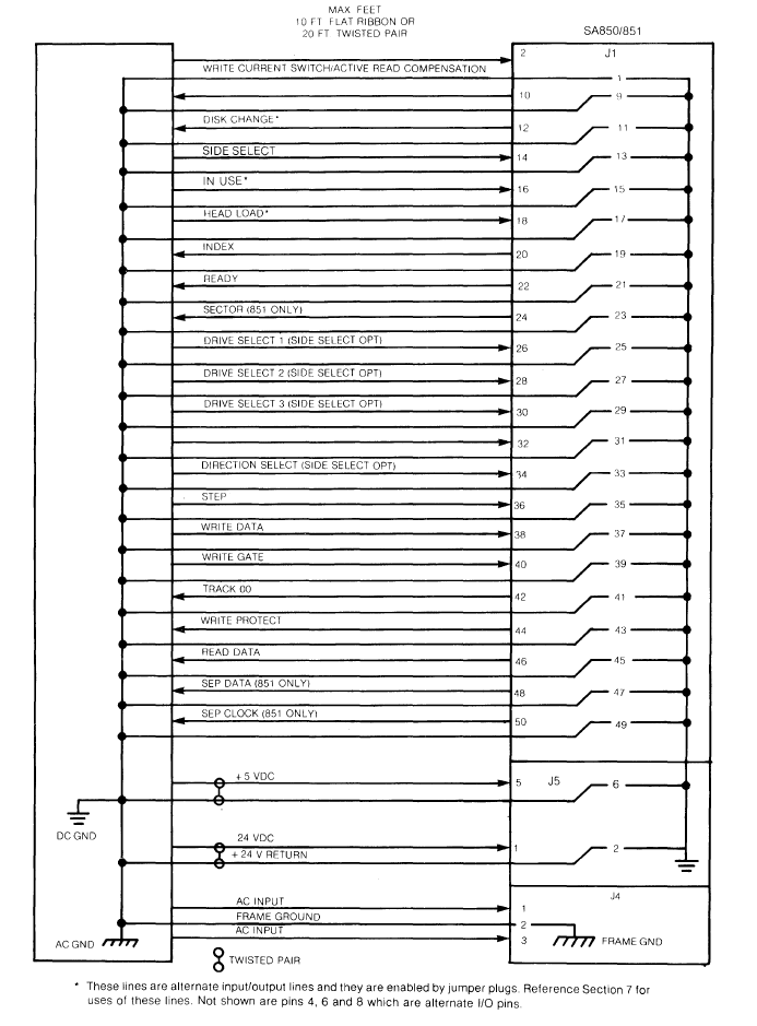
Shugart 8" Interface Connections (Industry Standard for 8" Drives)
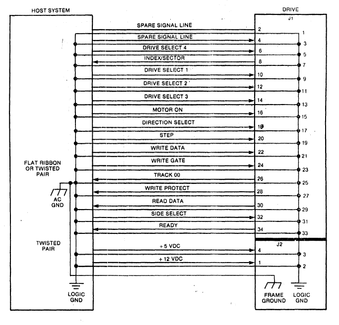
Shugart 5.25" Interface Connections (Industry Standard for 5.25" Drives)
Some vendors used own designs for interfacing the drive hardware. An example was Apple with their Disk II design, where Apple used a reduced drive hardware, while doing most of the work of the floppy controller chip in software, thus improving Apple's cost margine and at the same time allowing more flexibility with Apple's highly optimized disk layout. Which again prohibits reading or writing Apple Disk II floppies in a standard PC floppy drive. Maybe an early sign for Apple's ongoing view on interoperability with other ecosystems.
As long as only a single drive is connected to a controller, and the disk change information is not needed, the original Shugart bus and the PC floppy pinout are fully compatible. Most older drives (including the original Shugart drives) could be configured to drive1 to drive4 by jumper and simply connected with up to four drives to one cable, removing terminating resistors for all but the last drive in the chain. By using a special ribbon cable with some lines twisted between the connector for the first and the second drive, up to two standard PC floppy disk drives or original Shugart drives can be connected to the same PC floppy controller with so-called cable-select feature. The connectors are sometimes keyed to prevent wrong orientation (which normally is indicated by a drive constantly spinning even when not being selected).
The original IBM PC used NEC µPD765 or an Intel Intel 8272A or 82072A floppy controller chip, whereas other computers of the time utilized controllers from different vendors, such as the Western Digital WD1771 and WD1791. Due to differences in the capabilities, it may happen that media written with those controllers cannot be read with a standard IBM PC controller. One example is the use of address marks for ID and data fields, where the NEC and Intel controllers are restricted to certain predefined patterns.
All later floppy controller chips you can find in IBM compatible PCs are mostly descendants of, and backward compatible to NEC and Intel chips, so in general they share the same same basic set of registers and work in a similar way. Restrictions however apply to the capability to reliably read FM encoded single-density floppy disks, it is more or less a matter of luck whether the controller in your system is capable to read those disks or not. During the two decades when floppy disks had been the most prominent mass storage medium however many extensions and deviations were implemented, and the BIOS code for floppy disk I/O for sure is one of the more complex ones. Even within Windows 9x/ME, floppy transfers could freeze the whole system.
Typical problems with floppy disks include misalignment (either azimuth or angle) of the read/write head, too much abrasion from the magnetic oxide aggregating at the read/write head, and wear on both the medium and the read/write head. Deviation from the correct rotation speed can be compensated to a small extent, but also can cause problems when going too fast or too slow. Magnetization of the read/write head can happen, also can data on floppy disk media be erased when moving the floppy disk too close to a magnetic field. Lubrication of the actuator mechanism can disintegrate, which may lead to non-smooth actuator movement or even to a blocking actuator. Floppy disk drives with two read/write heads are more prone to problems than those with one single read/write head, since it is easier for single-sided disk drives to keep the right pressure of the read/write head towards the medium. In general dirt or dust and even fingerprints on a floppy disk can result in data errors. Of course loss of spindle or stepper motor function or sensor defects all result in total malfunction of the drive.
As a summary, pretty much can fail, and actually there are more reliable and more durable storage technologies than floppy disks. By the way, 8" floppy disks show to be more reliable than 5.25" floppy disks, and 3.5" floppy disks have the least reliability. Which is not really surprising.
HP Floppy Disk Formats
In principle, the HP 9845 just supports three different floppy disk formats, that of the 9885, that of the 9895A floppy disk drive, and single-sided IBM 3740 media. All form factors are 8" (5.25" drives were invented in the mid-seventies, but were not yet considered as an alternative at the design time of the 9845). So for gaining access to a standard HP 9845 floppy disk from your PC, you'll also need an 8" floppy drive for your PC.
Actually, since I personally don't own one, I just can hope that Fdio works with those 8" drives, but I never tried. So some feedback would be great.
Floppy disk support can be extended for the HP 9845 by installing an admittedly rare option ROM from Structured Software Systems. With such an option ROM installed, the 9845 can use any AMIGO based floppy disk drive, including those with 5.25" and 3.5" form factor. The media produced with this combination can generally be handled by the Fdio program.
The later HP 9000 Series 200 systems had built-in 5.25" floppy disk drives which used the same format as the 82901 external floppy disk drives. Both used double-sided, double-density drives with 40 tracks/48 tpi from Tandon or MPI. The first drives which could handle 3.5" floppy disks were the 9121 external floppy disk drives. Later the 9122 floppy disk drives supported the 3.5" DD and HD formats, but already used the SS/80 command set. Generally, for LIF floppy disks HP mainly used the 5.25" and the 3.5" form factors. All those disks can be handled with Fdio.
All HP floppy disks (at least until the entry in the PC compatibles) use a sector size of 256 bytes. The formats are summarized in the following table:
| Drive | 9885 | 9895 | IBM 3740 | 82901 | 9121 | 9122D/S | 9122C |
| Form Factor | 8" | 8" | 8" | 5.25" | 3.5" | 3.5" | 3.5" |
| Track Density | -- | -- | -- | low | high | high | high |
| Capacity | 502.5 | 1,155 kBytes | 240.5 kBytes | 280 kBytes | 280 kBytes | 616 kBytes | 1,232 kBytes |
| Cylinders | 67 | 77 | 74 | 35 | 70 | 77 | 77 |
| Heads | 1 | 2 | 1 | 2 | 1 | 2 | 2 |
| Sectors | 30 | 30 | 26 | 16 | 16 | 16 | 32 |
| Start Sector | 0 | 0 | ?? | 0 | 0 | 0 | 0 |
| Sector Size | 256 | 256 | 128 | 256 | 256 | 256 | 256 |
| Data Rate | ?? | ?? | ?? | 500 kbps | 250 kbps | 250 kbps | 500 kbps |
| GAP3 (access/format) | ?? | ?? | ?? | 27/84 | 32/50 | 32/50 | 14/54 |
| SR/HUT | ?? | ?? | ?? | 0xdf | 0xdf | 0xdf | 0xdf |
| Interleave (default) | 5:1 | 7:1 | ?? | 2:1 | 2:1 | 2:1 | 2:1 |
| Head Skew | -- | ?? | ?? | 2 | -- | 2 | 2 |
| Cylinder Skew | 5 | ?? | ?? | 2 | 4 | 4 | 4 |
| Encoding | M2FM | M2FM | FM | MFM | MFM | MFM | MFM |
DOS Floppy Disk Formats
The original IBM PC used double-density, double-sided drives from Tandon (the same as those in the HP 82901 or Series 200), but with different low level formatting with 512 bytes/sector, which became the standard also for later DOS formats.
Just for comparison, here are the characteristics for common DOS floppy disk formats:
| Drive | 3.5" |
5.25" |
||||||
| DS/DD | DS/HD | DS/ED | SS/DD | SS/DD | DS/DD | DS/DD | DS/HD | |
| Form Factor | 3.5" | 3.5" | 3.5" | 5.25" | 5.25" | 5.25" | 5.25" | 5.25" |
| Track Density | low | high | high | low | low | low | low | high |
| Capacity (kBytes) | 720 | 1,440 | 2,880 | 160 | 180 | 320 | 360 | 1,200 |
| Cylinders | 80 | 80 | 80 | 40 | 40 | 40 | 40 | 80 |
| Heads | 2 | 2 | 2 | 1 | 1 | 2 | 2 | 2 |
| Sectors | 9 | 18 | 36 | 8 | 9 | 8 | 9 | 15 |
| Start Sector | 1 | 1 | 1 | 1 | 1 | 1 | 1 | 1 |
| Sector Size (bytes) | 512 | 512 | 512 | 512 | 512 | 512 | 512 | 512 |
| Data Rate (kbps) | 250 | 500 | 1,000 | 300 | 300 | 300 | 300 | 500 |
| GAP3 (access/format) | 27/80 | 27/108 | 27/83 | 42/80 | 42/80 | 42/80 | 42/80 | 27/84 |
| SR/HUT | 0xdf | 0xdf | 0xdf | 0xdf | 0xdf | 0xdf | 0xdf | 0xdf |
| Interleave | 1:1 | 1:1 | 1:1 | 1:1 | 1:1 | 1:1 | 1:1 | 1:1 |
| Head Skew | 0 | 0 | 0 | -- | -- | 0 | 0 | 0 |
| Cylinder Skew | 0 | 0 | 0 | 0 | 0 | 0 | 0 | 0 |
| Encoding | MFM | MFM | MFM | MFM | MFM | MFM | MFM | MFM |
The Fdio Utility
Fdio just handles the raw sector data and doesn't care about any file system information. The main job for Fdio is to save the low-level floppy data into binary image files and, in turn, restore original floppy disk media from binary images. Besides, Fdio provides typical media operations like formatting, duplication and diagnostics. Finally, Fdio has the ability to perform a deeper analysis of unknown media in order to determine the medium characteristics.
All functions have been implemented into one single executable, which runs as a console application under all WIN32 versions from Windows 95 up to Windows 10. For direct floppy access under Windows NT/2000/XP/Vista/7/8/10 the free FDRAWCMD driver package must be installed (the package was developed by Simon Owen and is included in the distribution packages which can be downloaded below, more information about the FDRAWCMD driver can be found here).
Getting Started
The Fdio utility does most of the work automatically, so you for example can copy a floppy from drive A: to drive B: (no matter what kind of medium is inserted) simply with
fdio -dup a: b:
If you want the same copy but to an image file instead of a real floppy drive, you can create a disk image e.g. with
fdio -dup a: myimagefile.hpi
Transferring an image back to a floppy disk is done with
fdio -dup myimagefile.hpi a:
Copying to floppy requires a floppy already to be properly low-level formatted (note that all existing data on floppy will be erased during this step). This is done simply with
fdio -format a:
Note that there are many different low-level formats supported (this is one of the main advantages of Fdio). If you do not select a specific format, Fdio assumes DOS format and formats to the most recent format supported by your floppy drive hardware. If you need to format with a special format like single-sided double-density 3.5" LIF format, first execute
fdio -preset
Then select the preset number of your choice, and add it as -p parameter to the format command. For the SS/DD LIF example, it would be
fdio -format -p 11 a:
After formatting, a floppy is ready to be used for copy operations.
Using the Fdio Utility
Fdio can be widely tailored to your needs. Generally, it can be executed in the form
fdio <command> [<options>] [<parameters>]
Below is a summary of all commands. Execute Fdio with the -h option for a summary. Also have a look into the README file for up-to-date information.
| Command | Description |
| -format <drive> | Low level formats a floppy disk. |
| -dup <source> <target> | Sector-by-sector copy from <source> to <target>. <source> and <target> can either be drives (e.g. a: or b:) or images (select an image file name in this case). Can be used to duplicates media, to create images from media or to restore media from images. Normally, duplication works with ordered sectors, i.e. the sector data is arranged in the sequence of the sector IDs. It can be switched to reading raw track data with the -raw option. The duplication range can be limited with the -r option. |
| -verify <drive> | Performs a sector-by-sector read verify on the floppy disk. All data on the disk will be preserved. |
| -info <drive> | Report the medium type (only works if there is already a preset for the medium, see the -preset command below). Note that the reported data reflects only the most likely preset, not the actual characteristics of the medium. Use the -analyze option for a comprehensive check of the medium characteristics. |
| -analyze <drive> | Performs a detailed medium format analysis in order to determine medium characteristics for own preset definitions. Can be used with any medium. |
| -describe <drive> | Creates a detailed map of the medium in XML format, including all structural information. Can be used with any medium. Every cylinder which can be positioned with your floppy drive hardware will be checked, so media with low track density in high density drives may lead to unpredictable results for non-existent/intermediate tracks. |
| -preset [<preset>] | Shows details about a specific <preset>. If <preset> is omitted, all presets are listed. For the current 2.2 version this would show up to: Preset Media type 1 DOS 3.5 DS/HD (1440k) |
| -reset | Resets the floppy disk controller (can be useful if the controller has been left in an unkown state). |
| -license | Show license information. |
Most commands can be tailored with one or more options. Below is a summary of all available options. Again, execute Fdio with the -h option for a summary. Also have a look into the README file for up-to-date information.
| Option | Description |
| -h | Output a summary of the command line options. |
| -d <drive> | Specify the drive type which is used in the operation (overrides BIOS settings). <drive> is one of
Can be useful in case your OS or BIOS reports wrong drive types or the OS doesn't detect a connected drive. This setting is valid for any drive used in the operation. So, if you for example are using the -dup command to copy from one drive to another, the selection applies to both drives. |
| -l <loglevel> | Specifies detail of Fdio's reporting. Possible values are Loglevel 4 applies to direct controller action only (available under Windows 9x/ME). Also, for reliability reasons, no output will be generated for burst transfers due to timing restrictions (the output would disturb the contiuous transfer of disk data). Controller communication can't be tracked with the FDRAWCMD driver. |
| -p <preset> | Use a predefined preset instead of the default (see the -preset command above) |
| -g <c,h,s,size> | Specify the disk geometry for known media (overrides any autodetection) with the following parameters:
c: cylinders per disk |
| -i <interleave> | Specifiy the n:1 interleave factor (overrides autodetection). |
| -s <headskew> <cylskew> | Specify head and cylinder skew (overrides autodetection). |
| -r <first> <last> | Specify a range for dup. <first> denotes the first 256-byte-block (starting at 0), <last> the last 256-byte-block (inclusively). If the sector size is higher than 256 bytes, partial sector copy is possible. As an example, if you need to copy the second and third sector from a disk in <drive> with sector size of 512 bytes into <file>, use
and only blocks 2, 3, 4 and 5 (covering the second and third 512-byte sector) will be copied. |
| -raw | Use raw track access mode for dup (read only). In this mode, the sector ID is ignored and the sector data is just read in the order they are placed on the track, including any junk sectors. |
| -v | Show version info. |
| -license | Show license info. |
There are several often-used presets for different vintage floppy formats built into the Fdio utility which are used for autodetecting the floppy format. Execute 'fdio -preset' to show the supported presets. If you like to add some more, simply create a config file with the name fdc.ini. There is a sample file fdc_example.ini included in the distribution. Executing 'fdio -analyze <drive_number>:' will help you finding the right parameters for unknown media.
How Fdio Works
As mentioned above, the main objective of the Fdio program is to recover sector data from non-standard floppy disk media in proper sequence. It is not the aim of this program to register all structural information of the media (e.g. for exact reconstruction of the original disk) or to break copy protection. Use programs like Copy II PC or Teledisk for this purpose. On the other side, you in general can't use tools like Teledisk for extracting the original payload data.
The Fdio model assumes a uniform drive geometry and uses the first track as master. Any track which deviates from the first track (e.g. in sector count or modulation) is treated as 'junk' in order to separate valid payload data from other information, which is of no use for storing information data. So, if the original format uses different modes/geometries for different tracks, this can't be handled by Fdio. This differs from other solutions, which are dealing on sector level and in general don't care about what data is usable and what is used for copy protection or simply junk (e.g. from previous formatting).
In normal mode, the first thing Fdio does before any operation is to get the floppy drive data from the operating system. Since on a PC it is technically not possible to determine reliably whether a drive is connected and which are the form factor and the capabilities of the drive, we rely on the data once specified by the user in the system BIOS. In case the drives are not reported correctly by the OS or BIOS, you can use the -d option to specify the type of drive installed on your own.
For read, write and verify operations, Fdio next tries to detect the proper medium characteristics. To do it quick, Fdio tries to read the first track with all medium presets matching the form factor in the order they are listed with the -presets command. The first working preset is then used for any further read or write operation. In case you need to use another preset, use the -p option to select your own or one of the -g, -i or -s options to override the detected settings. If you are always using the same preset, simply disable auto-detect in the fdc.ini file by using the 'preset=' directive.
Once the proper medium parameters are set, Fdio reads or writes all valid sectors in the proper order to/from other drives or image files, ignoring everything else. So images represent the net payload data stored on the medium, without any structural information.
Depending on the Windows version, Fdio can either go directly on the floppy controller, or can use the FDRAWCMD driver for low-level floppy access. Both methods have their advantages and disadvantages. Actually, the way Fdio goes down on the floppy controller under Windows 9x/ME is more or less a hack, since it utilizes neither DMA nor interrupts.
Direct controller access gives most control over the hardware, but works under Windows 9x and ME only, since the NT driver model protects the low-level hardware. Fdio does not use DMA for direct controller access, so for making sure the critical part of the data transfers from the controller to the host is not disturbed by any user or program action, Windows interrupts will be partly disabled, as you can recognize by short 'freezed' mouse movement. In general this should not be an issue, since control is quickly passed back to the host, however if the floppy controller gets locked up for whatever reason, it can happen that Windows gets stuck, too.
In fact I am convinced Simon Owen did a real good job with his FDRAWCMD driver package, so I encourage to use this way as the preferred and more reliable choice.
Restrictions
As mentioned above, Fdio does a quick check to find out the proper medium format (autodetect) based on the very first track only. So, if the other tracks won't match the format of first track, or the format is not yet in the list of supported formats, Fdio does not work out of the box with that disk. Also, Fdio assumes a constant sector size for all sectors on the disk. So, if there are - for whatever reason (optimized yield, copy protection etc.) - sectors with changing sector size, only the sector size of the very first sector in the first track is regarded as "valid", and all sectors deviating from that size are regarded as "surplus" or "junk". This especially prevents Fdio from supporting so-called mixed sector size (MSS) formats.
Reason behind is a trade-off. Autodetection on MSS obviously is not possible, you need to scan the whole disk and create full sector maps. Also it is not known in advance, whether the extra sectors hold valid data or not and whether they are the result of a valid formatting process, or just left over from a previous formatting run (typical case is a dual-sided formatted disk being re-formatted in a single side disk drive). And, finally, if you create images from the drive, you are forced to also register and keep the full sector structure in addition to the net data, otherwise you will not be able to re-create the floppy.
For the sake of ease of use, Fdio assumes a homogeneous disk layout, which allows both autodetect and use of pure unstructured net data images. If you need to preserve the full structure of a floppy disk, it is recommended to use tools like Teledisk.
Analyzing Media
The presets provided with the Fdio program cover the common DOS formats plus the formats used with vintage HP floppy drives (mostly used with the LIF file system). This is ok for the context of this site, however you may like to use Fdio with some other formats. Also, the provided presets may fail even on expected DOS or LIF disks, for whatever reason.
If you know the characteristics of the disk format you are using, you can create your own presets and add them to the fdc.ini file. Fdio also provides some kind of analysis for unknown media in order to let Fdio determine those characteristics for you. Simply run Fdio with
fdio -analyze <drive>
and Fdio will do a sophisticated check of the medium, providing you with the preset data you need. Take into account that even this kind of analysis has its limits. Fdio still assumes a uniform geometry and the same encoding (FM/MFM) all over the floppy disk, and not all tracks are completely analyzed (Fdio does a probe check in three dimensions - sectors, heads and tracks, and therefore does its job quite fast but does not check all sectors of the medium). Also, floppy media still can hold data from previous formatting, which differs from the current format. Copy protection mechanisms can make it even harder to get some meaningful information about the disk. Altogether, Fdio does its best to provide you with the data needed for working with the disk, but it may fail anyway.
If you need a complete map of the medium, with all sectors and tracks, use the -describe command:
fdio -describe <drive>
Fdio then creates a list of all tracks with a comprehensive description of all structural information in the following notation:
<cylinder num=...>
<head num=...>
<sector ... />
<sector ... />
...
</head>
<head num=...>
<sector ... />
...
</head>
...
</cylinder>
This can be helpful for fault analysis in case the -analyze option does not lead to usable results. When using Fdio with the FDRAWCMD driver under Windows NT/2000/XP/Vista/7/8/10, the results however can be somewhat strange for disks with low density tracks (40 tracks per side and less).
Working with Floppy Disk Images
Those images produced by the Fdio utility (or by HPDir) are 'cooked' images and identical to those produced in Unix/Linux with the dd command. In contrast to 'raw' images they hold the actual payload data from each floppy disk sector in correct sequence. This means that no structural information is stored with the data, and you don't have to care about interleave, track/cylinder skew, extra spare sectors or such alike.
Files of this format should have the file extension '.hpi' to indicate they have been derived from HP disks, so that someone knows that the files system contained in the data probably is HP-related. However there is nothing magic with this format, it simply represents the uncompressed data how it is provided to the operating system (which won't care about low-level raw matters as well). If you open the image file with a hex editor, it looks much like when you are using a disk editor on the floppy disk. If the sector size is e.g. 512 bytes, the first 512 bytes of the image file are the content of the first sector on disk, the next 512 bytes are the content of the second sector on disk and so on. Pretty generic.
In fact, the image format used by Fdio is identical to that used by other utilities available from different vendors, like VirtualFloppyDrive (VFD, free), Floppy Image Creator (shareware), EMT4WIN (free), Rawrite (free) or WinImage (shareware) and a couple of others. The images with different file name extensions like .vfd, .ima or .img actually are all the same, so - supposed you have created the image with Fdio from a Windows or DOS floppy (i.e. using a FAT, FAT32 or NTFS file system) - you can use Floppy Image Creator or WinImage to explore the image produced by Fdio or VFD to mount the image as virtual floppy drive.
Be aware that all those utilities only support Microsoft's DOS/Windows file systems, some also can deal with UNIX file systems, but none with vintage HP file systems. So attempting to explore an image file created from e.g. a LIF floppy disk with WinImage won't work. Use the HPDir utility or the HPDir plugin for Total Commander from this site instead (see HPDir Project Section).
Downloads
Click here for downloading Fdio:
| Fdio 2.2 Windows 9x/ME/NT/2000/XP/Vista/Win7 executable: | fdio-22.zip |
This version may still have a bugs. Please use the contact feature to let me know if something doesn't work as expected.
This program is not free software, however non-commercial use is provided without charge and you can redistribute it under the terms of the CREATIVE COMMONS PUBLIC LICENSE as published by Creative Commons International, either version 3.0 of the Attribution NonCommercial NoDerivs License, or any later version.
Troubleshooting
See the README included in the Fdio package for troubleshooting procedures.