The 9845 Software Architecture
The 9845 software concept splits into two parts, one for the PPU and one for the LPU. Common for both parts is that the complete OS software is implemented as firmware and stored into ROMs. This includes the I/O routines, the process scheduler and the BASIC language development and runtime environment.
Like the system architecture, the software architecture was not completely new. Many components and concepts were derived from earlier designs (e.g. from the 9830 and the 9825) and enhanced for use in the 9845 systems.
There is no bootstrap or boot-up loader routine which requires loading parts of the OS from mass storage, so the whole system functionality is almost instantly available after power-up. At design time of the 9845, this was considered as an important feature of a desktop system (in contrast to the minicomputers). Take into account that in the late 70's, computer knowledge was much more voodoo than today, and the start-up and shut-down procedures of mid-size computer systems already needed some more knowledge than powering up a PC today.
On the other side, a certain amount of flexibility was sacrified when an incremental boot process had been abandoned. However, one have to keep in mind that the 9845 wasn't designed for continuous operation, it was assumed to be operated in an office environment, and the system was too power consuming (and too noisy) to be up all the time. So the instant-on feature was a real benefit.
After power-up, a special circuit in the 9845B/C determines whether there is ROM present in block octal 45 (the test ROM block). If ROM is found, execution starts in this block at address octal 40. If not, PPU and LPU start execution at the next location (address octal 41) in block 5 (the PPU ROM block). Note that the 9845A uses block 1 for both PPU system firmware and R/W memory (there is no block number above 3 for the 9845A), so execution starts at block 1 anyway. Part of this code is to identifiy which processor is LPU and which is PPU and to branch accordingly into either the PPU or the LPU firmware code.
Now both processors play their role, and each with its own software concept, but still working closely together.
The PPU Firmware Architecture
PPU processing is basically controlled by a task scheduler and a couple of interrupt handlers. The scheduled tasks are performed in concurrent process structures, whereas the interrupt processing is event-driven. Tasks are created and terminated in communication with the LPU processor.
The actual way how communication is performed between LPU and PPU is a bit complex. The basic principle is, that the LPU may create I/O tasks either under program control or interactively, handle them over for further processing to the PPU, and either go on with the current program (overlapped mode) or wait until the I/O task is finished (serial mode).
Generally I/O tasks use data buffers at the LPU side and device buffers at the PPU side. A simple PRINT command first creates an I/O task for the PPU, and while the data buffer is filled by the LPU, it is concurrently processed by the PPU and communicated to the appropriate device. So LPU and PPU share all the work which speeds up the whole processing significantly. For example, while the LPU is evaluating the expressions for the data, the PPU does all the formatting for the data which is already produced.
So far the procedure should be comprehensible. In fact, the PPU can (in contrast to the LPU) process more than only one task at a time. The reason is that I/O tasks generally overlap. Once a data transfer is started, the system shall still be able to accept user input etc. This leads to a concurrent execution scheme which is implemented through so-called I/O processes.
The thing with the processes is as follows:
The PPU has one special structure called the QTABLE, which holds for each device selection code a seperate process queue and a device buffer. For each new I/O task, a new process in the appropriate queue is created. What the process scheduler does, is going through all the devices in the QTABLE and check whether the first process in each process queue is in the appropriate state for execution (means something has to be done). If this is the case, execution is passed over to the specific routine which is associated to the process. When finished, control is returned to the process scheduler which examines the next device in the QTABLE for an active process. The process scheduler is also responsible to resolve possible conflics with certain concurrent tasks (e.g. reject DMA requests when a DMA transfer is already in progress).
In order to simplify inter-process communication, all processes are linked into a hierarchical tree structure with father, son and brother processes (all very unfeminine, which mirrors the engineering staff formation of that time). Most information about a process, including the father/son/brother links and the address of the associated execution routine, is held in a 10-word process control block (PCB) structure, which is created for each new process and removed with process termination.
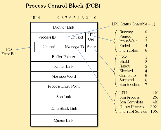
Process Control Block (PCB) Structure
Note that the scheduler didn't work with preemptive time slices (like a real multitasking system), but with the principle of cooperative multitasking, similar to older Windows versions. So if an I/O process is locked up, the PPU and finally the whole system sooner or later stops responding (this is then the right time for CONTROL-STOP).
The I/O data transfer normally is controlled, but not actually performed, by the I/O processes themselves. The real work is done either by interrupt handlers (which were again set up by the I/O processes) or, for more efficient mass data transmission, via DMA.
In addition to the I/O processing decribed above, there are a couple of other requests which can be issued either from the LPU to the PPU or from the PPU to the LPU, but which are not covered here.
The LPU Software Architecture
The LPU is operating in three modes: program editing, program execution, and interactive user input. The two latter tasks can be performed concurrently, so that user input can be performed while a program is running. It is not possible to run two programs at the same time, however is is part of the concept to pass tasks to the PPU and either wait until the PPU has completed the task or immediately continue program execution. The latter is called "overlap mode" and can result in a much faster program processing. In the other direction, the PPU can be requested to pass interrupts over to the LPU, which then pauses its normal program execution for interrupt processing.
The LPU software concept is strongly oriented towards the processing of BASIC instructions. For the system, there is only a marginal difference between executing commands during user input or during program execution. There is an interpreter routine, which takes the command, looks up the command in a linked list of command routines and performs some command specific syntax checking. The main difference is that interactively entered commands are immediately executed after the sytax check, whereas during program edititing execution is postponed until the program is run. The appropriate machine code subroutines for command execution are the same.
So the LPU software architecture mainly consists of the program editor, the syntaxer, the user program in form of a sequence of BASIC commands, and the BASIC command routines for command execution. The latter are normally placed in ROM (either system ROM or option ROMs) but can be extended dynamically through so-called binary routines. For the system it makes almost no difference whether the commands have their execution code in the system firmware, in option ROMs or in binary routines, except that there is an order in which those storages are searched for the matching keyword.
All instruction keywords are kept in linked lists. There is one list for keywords implemented with binary routines, one list for keywords implemented with option ROMs, and one list for the keywords implemented in the LPU system ROM. If a command is entered (either as instruction in a BASIC program or interactively), the three lists are searched for a matching keyword in the above order. If a match is found, the appropriate command routine is processed.
This makes binary routines quite interesting, since it is the best way to gain complete control over the LPU. And, since keywords in the binary routine list are checked first, it is even possible to redefine existing firmware commands. Unfortunately, there is no equivalent way to install or exchange similar custom routines for the PPU. The only way to expand the capabilities of the PPU (including system level device drivers) is by installing option ROMs*.
*This is the standard way, however it can be assumed that the 9845 OS can be hooked towards custom driver routines. Unfortunately too little information is available about the PPU system vectors unless a commented assembler listing is available.
The BASIC Interpeter
The BASIC interpreter works both as user interface (in terms of a command shell) and as program execution environment. The statements which can be entered directly differ only slightly from the instructions which can be executed under program control. The interpreter is partly deactivated during program editing, however the syntax checking will still be performed with each entered program line.
One of the design guidelines for the BASIC interpreter was to create as few execution overhead as possible, and so providing best-possible execution performance. Most BASIC interpreters use a token scheme to store the BASIC program in a compact internal form, and schedule the appropriate executable code during runtime. One of the reasons for the high performance of HP BASIC is that HP used for the 9845 a slightly different approach. Instead of holding the program in tokenized form in memory, each command is internally represented by the address of the executable routine plus a data block for the parameters (data or symbols).
This avoids time consuming scanning and searching and thus accelerates program processing, but sacrifies flexibility in terms of up- and downward compatibility. In order to re-gain compatibility, it was possible to save BASIC programs verbosely as ASCII code (file type DATA). When transferring to another system, the ASCII program listing could be loaded with the GET command and then STORE'd in the specific format again. The drawback was, that the appropriate 9845 system must had been available if there was just a STORE'd BASIC program and no ASCII version. This is the main reason why 9845A BASIC programs won't get loaded on a 9845B/C system unless you have an ASCII file of type DATA. Another drawback of the verbose ASCII storage format was that the files became much larger and were much slower to load (also because they had to be re-parsed and syntax-checked).
It is not clear whether the 9845 used a vector scheme for addressing at least some of the OS or BASIC execution routines. Some routines seem to use such a vector based indirect addressing and some don't.
Below is the generic format for storing BASIC program lines in memory:
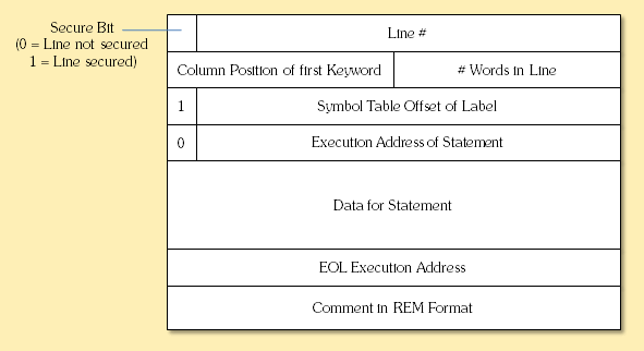
BASIC Program Line Format
One word to the display use within BASIC: All HP BASIC versions up to TransEra's HTBAsic have in common, that the screen is split into several areas, i.e. a print area, a display line, a keyboard entry area, a line for system messages and an optional soft-key label area. Actually those areas are addressed as different pseudo devices, the print area has the select code 16, the display line the select code 17, and the system message line the select code 18. This may appear unconventional with respect to most other BASIC implementations, however it doesn't take long to get comfortable with this unusual feature.
The BASIC editing mode is an example for a program which overcomes this restriction, the whole print area is used for the display of the program text, with one interactive input line in the center. However, the editing mode is unusual as well compared to the generally modeless full-screen editors of other BASIC implementations.
Binary Routines
Binary routines are precompiled (machine code) implementations of custom instructions. Each binary routine can contain an arbitrary number of instructions or keywords, all implemented with the same structure:
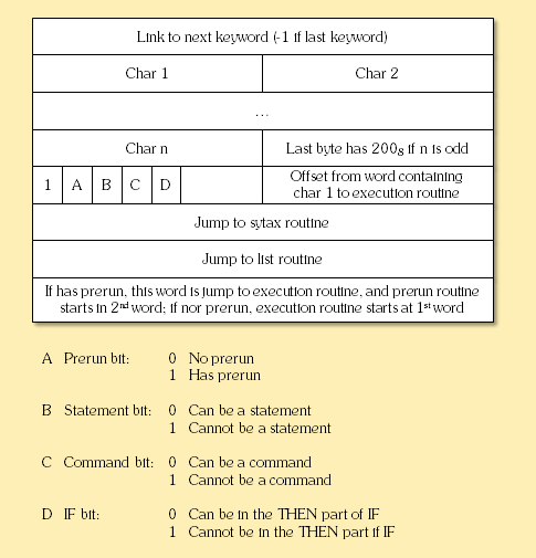
Primary 9845 Keyword Structure
Each instruction block starts with a link to the next instruction block (16-bit address word). Next an even number of bytes contains the instruction keyword. If the keyword contains an odd number of characters, the last byte is filled with a value of octal 200. The next word contains an 8-bit offset from the start of the keyword to the execution routine in the LSB and a number of control flags in the upper 5 bits of the MSB. Next the block contains machine code jump commands to the syntax checking routine and the listing routine for this specific command. The jump command to the listing routine is either followed by the execution routine routine, or, if the prerun flag is set, by a jump to the execution routine, followed by the prerun execution routine.
The control flags indicate whether the keyword has a prerun routine (PRERUN bit), whether it can be used as a statement in a BASIC program (STATEMENT bit), whether it can be used as interactive command (COMMAND bit, and whether it can be in the THEN part of an IF clause (IF bit).
The instruction blocks can be chained, the last instruction in the chain points to -1 (octal 177777) as the next instruction.
Binary routines were saved on mass storage in a special file format, which added a header structure to the binary routine. The header structure included some hints about the size, type and original location of the binary routine.
Creating your own BPRG files certainly is of high value. I'm not yet sure about the meaning of all values in the BPRG file header, but I will publish them as soon as I figure them out (see the Binaries section for a list of known binary programs and the header structure as far as I have an idea of it).
Binary routines can be stored and loaded either separately in a file of type BPRG with the LOAD BIN/STORE BIN commands or, alternatively, in combination with a BASIC program as PROG type file with the LOAD/STORE commands. With the latter method it is possible to store a BASIC program with all its command extensions in one single file.
There is a special memory area where all binary routines are located. Binary routines will not be erased with a plain SCRATCH command, but with a SCRATCH P or SCRATCH A command. Binary routines can be loaded incrementally one after the other with subsequent LOAB BIN commands, however when using the STORE BIN command, all binary routines currently in memory will be saved together into one single file of type BPRG. In some aspects, binary routines are very similar to the terminate-and-stay-resident programs (TSR's) used in MSDOS.
When loading binary routines, they are automatically linked into the keyword chain, so that they can be invoked both interactively or as a statement in a BASIC program. Since the binary routine keyword list is searched before the option ROM or system ROM keyword list, binary routines can even redefine existing keywords.
Other Programming Languages
There were only a few language packages available for the 9845 to replace the built-in BASIC interpreter:
- First there were two 9845 assembler packages: HP's Assembly Execution and Development ROM, and the IEM Macro-Assembler. Both were designed for use with high-level languages. The Assembler Execution and Development ROM was completely intergrated in the BASIC development environment (i.e. not really a replacement but an add-on), whereas the IEM MAcro Assembler worked within the Program Development System (PDS 45) from IEM.
- Next, there were the IEM Pascal and IEM Fortran 77 implementations, both for use within the Program Development System (PDS 45) from IEM.
- Finally, the Forth language was available from the exchange library program.
PDS 45 was a disk based operating system from International Electronic Machinery, Inc. (IEM) with file handling capabilities, run-time support routines, block I/O service routines, a screen-oriented editor with both program and text editing capabilities, a file handler and a link editor for linking user programs with precompiled programs and language-independent libraries.
The Filesystem
The 9845 filesystem basically consists of three sections, a system block, a directory, and the file area. The system block holds media information like file system ID, medium size and geometry, interleave factor, and pointers to the other file system information on the medium. The directory block includes one file descriptor entry for each file, holding the filename, the file size and type, the defined record size for this file, protection information, and the location of file data in the file area. Disk media generally includes also a file allocation table between directory and file area, where all free data blocks of the file area are listed so that suitable free storage areas can easily be located (see the HPDir Project section for more information on the file system).
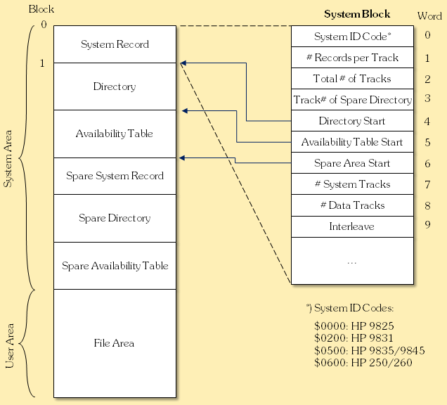
Overview 9845 Disk File System
Instead typing files with a filename extension (like it is done in MSDOS), the file type is explicitly denoted in the file descriptor with an appropriate file type code. Filenames can be composed from up to six characters and were case sensitive. All characters can be used except the colon, the quote mark, and the ASCII character codes 0 and 255. Blanks are just ignored.
Unfortunately the 9845 file system does not support subdirectories, which makes it sometimes hard to maintain an overview when the file number gets too large.
The internal structure of the file of course depends on the type of the file. Basically, all files were just a sequence of so-called physical records of 256 bytes each. Above this physical structure, the whole file is divided into so-called defined records of equal size, which have no direct relation to the underlaying physical records. The defined record size can be any even number between 4 and 32,767. All data items or objects are stored in those defined records, the physical record structure is not visible, at least not for the BASIC prgrammer.
The logical structure above the defined records (i.e. the data objects and their representation) is up to the application which is using the file type, however some file types already have been defined.
The predefined file types are:
| File Type | File Type Code* | Purpose |
| BKUP | 0000 | File type for backups (used with the DBMS ROM) |
| DATA | 0400 | General pupose data container (this is the standard data file type for BASIC programs, and as well used for portable BASIC programs saved in ASCII format) |
| PROG | 0800 | Standard file type for storing BASIC programs in a compact, but system specific format |
| KEYS | 0C00 | File type for saving special function key definitions/macros |
| BDAT | 1000 | File type for packed binary data as used by the FREAD and FWRITE statements (available with the Mass Storage ROM) |
| ALL | 1400 | File type for saving complete system dumps (including loaded programs, variables, key definitions, binary routines, and display content) |
| BPRG | 1800 | File type for saving binary routines (all currently loaded binaries are saved into one file) |
| OPRM | 1C00 | General purpose container for all other option ROMs, the data structure is defined by the option specific ROM (note: the object code file produced by the assembler is of this type when stored on tape instead of disk) |
| ROOT | 1C80 | File type for data base root file (same code as ASMB above, used with the DBMS ROM) |
| DSET | 1D00 | File type for data base file containing a data set (used with the DBMS ROM) |
| WORK | 1D80 | Use unknown |
| ASMB | 1E00 | File type for saving object code routines produced with the Assembly Execution and Development ROM |
| FORM | 1E80 | Use unknown |
| TEXT | 1F00 | Use unknown |
| TYP1 | 1F80 | Use unknown |
*hexadecimal result of masking word 6 in disk directories with hex 1F80. File type codes for tape directories are the same, however only the high byte is used as a single byte code.
Additional file types can be defined by any application as needed, however the file types described above are the only ones which will be properly listed with a CAT statement, and it is important when defining new types not to use one of the predefined file type codes.
Because of the special importance of the DATA files, the structure of those files is described in the section below.
DATA files
Files of type DATA are the standard container for any data used in BASIC programs. They consist of an arbitrary number of data items or objects like strings, integers or floating point numbers.
Each data item occupies a certain number of 16-bit words, either with variable size like strings, or with fixed size like integers (two words) and short precision floating point numbers (also two words), or full precision floating point numbers (four words). All data items hold header information from which the type of the data item can be derived.
In priciple, all data items are just stored in sequence inside a defined record. Once one defined record has been filled, the next data item is stored at the beginning of the next defined record. No data item can cross defined record boundaries. If there are not enough words left in a defined record to place the whole data item into that record, the space is left unused and the item is placed at the beginning of the next defined record.
Strings can become pretty large and therefore spread over a larger number of defined records. Obviously, they require special handling.
Generally, different data items are defined for a string or a part of a string, depending of whether
- the string fits completely into one defined record,
- the substring is the leading part of a larger string which crosses a defined record boundary,
- the substring is the middle part (filling the whole defined record) of a larger string which crosses a defined record boundary, or
- the substring is the last part of a larger string which crosses a defined record boundary.
Each case has its own data type, so the full string can be reconstructed by combining the substrings.
Logical record markers (EOR) can be placed after each data item in order to give the file a logical record structure. Also, a logical end-of-file marker (EOF) can be placed after the last data item or logical record marker in order to denote that no valid data comes behind. When creating new files with the BASIC command CREATE, the (empty) file is completely filled with EOF-markers, so there is no need to write them on your own.
| Data Type* | Item Size in Words | Description |
| 0A | 2 | Integer number |
| 1A | 4 | Full-precision floating point number |
| 0C | 1 < x < record size | Middle part of a string |
| 1C | 1 < x < record size | First part of a string |
| 2C | 1 < x < record size | Last part of a string |
| 3C | 1 < x < record size | Total string (fitting completely into one defined record) |
| 1E | 1 | End-of-Record (EOR) |
| 3E | 1 | End-of-File (EOF) |
| other | 2 | Short-precision floating point number (if right byte consists of two valid BCD digits) |
*hexadecimal result of masking the first word with hex 3E.
Especially text files are always stored as DATA file type. Each string can be as long as 32,767 characters. In contrast to a DOS text file, the DATA format doesn't separate the strings by CR/LF, but uses the data item structure described above. As a consequence, each string can hold all ASCII characters, including CR and LF, but strings which cross defined records boundaries have to be split when writing them into the file and re-composed when reading them from the file.
Programs saved with the BASIC SAVE command are always files of type DATA with defined record size 256 (equals the physical record size), containing all the programs lines as ASCII strings. This makes the program file portable for other systems.
9845 BASIC provides two types of access to DATA files: serial access and random access. In serial access, all data items are read just in the sequence they are stored in the file, and each READ or WRITE operation just positions the file pointer on the next item. In random access, a specific defined record anywehere in the file can directly be addressed without the need to step through the whole file.
Compatibility
Software for the HP 9835A/B, the HP 9845A and the HP 9845B/C if provided as HP Level I BASIC source code (DATA files with HP Enhanced BASIC) in general is interchangeable, as long as no BASIC language extensions from binary programs or option ROMs are used.
PROG files (compact BASIC storage format) are system specific and not interchangeable between 9835A/B, 9845A and 9845B/C. Use SAVE on the source and GET plus STORE on the target system to port PROG files.
BIN files (binary programs) are system specific and in general not interchangeable between 9835A/B, 9845A and 9845B/C, especially if they make use of system variables and extended memory address extension.
ASMB/OPRM files (assembler object modules) are system specific and not interchangeable between 9835A/B and 9845B/C. The 9845A does not support assembly language. Use SAVE on the source and GET plus ISTORE on the target system to port ASMB/OPRM files.
BPRG files (binary data files) are interchangeable between all 9835 and 9845 systems. DATA files, if not containing BASIC program code, can be interchanged also with 9825A/B systems.
Loading and Storing User Programs
Saving your own programs and using programs developed by others is essential for every computer system. Commercial software was available either as BASIC programs, or as binary programs (machine code), or both. Software was distributed either on tape cartidges (this was the standard way, since each 9845 had at least one built-in tape cartridge drive) or on 8" floppy disk.
BASIC programs could have been provided either as ASCII text (file type DATA), or in a more compact internal form (file type PROG). The latter form could be protected against program listing, which made it hard (but not impossible) to gain access to the actual code. There were companies which offered more secure protection methods as value-add. As already mentioned above, the DATA format was the format for compatibility, whereas the PROG format offered a machine specific, but compact and efficient type of program storage.
DATA files could be produced with the SAVE and loaded with the GET command. PROG file could be created with the STORE and loaded with the LOAD command. BASIC programs could use the whole available R/W memory, however the main program and each subprogram had to fit into a 32 KWord memory block. If the memory was not large enough to hold the complete program, parts of the program could be loaded and executed dynamically during run-time by program control.
The whole BASIC system was designed with access restriction to system resources as far as it seemed to be necessary to avoid program crashes. As side effect, the whole system firmware was relatively well protected against too much curiosity.
For convenience, the AUTOST key could be latched in order to load and execute a special PROG type file with the name "AUTOST" immediately after system initialization. In order to load and launch the program, the program file had to be on a tape cartridge loaded in drive T15.
In addition to the BASIC programs, with an Assembler Execution and Development ROM precompiled machine code modules could be created, which could be either stored as files of type ASMB or OPRM, depending on whether they were saved to disk or to tape. Those precompiled modules could be saved with the ISTORE and loaded with the ILOAD statements. The modules were no complete programs, but rather subprograms which could be called from within a BASIC program. However, even for loading and executing, one of the two available assembler ROMs (either Execution or Execution and Development) was required. Creating binary programs with the the Assembler Execution and Development ROM was not intended.
More Information
A good source for the 9845 overall architecture is the arcticle from the McGraw-Hill publication "Computer Structures: Principles and Examples" (look here for download), and additional details can be found in the 9845A patent (available here for download). Note that all this information applies primarily to the 9845A, however the software architecture should be basically the same for the 9845B/C.