Before First Turning On
Why and how
There are some things you should take into consideration before you power your newly acquired 9845 on. Remember, the systems may have been stored for decades without ever being switched on. Experience shows: SIMPLY POWERING UP MAY DESTROY YOUR SYSTEM !!!
Here are the main risks:
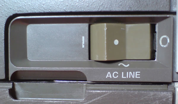
- The voltage selection switch may be in the wrong place (e.g. for 110 V instead of the 220V of your local power line)
- The power supply unit (PSU) is already defective and provides over-current or over-voltage to the rest of the system.
- Some of the PSU components are instable due to aging, powering up may destroy them and affect both the PSU and the rest of the system.
Just to give you an idea how it looks like when the AC line filter capacitors enter Nirvana:
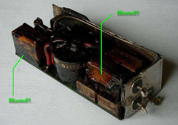
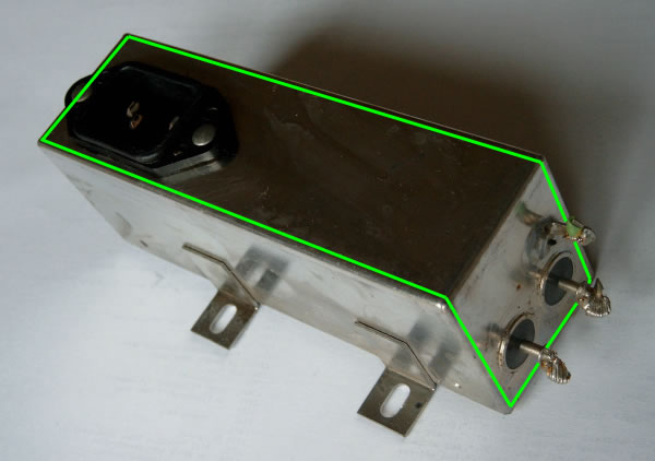
Blown AC Line Filter Module (this one is a 9845B/C Model 200 - 10A Type)
This blasted AC line filter module
- still belongs to the minor risks (since it is a component comparably far away from the other parts of the system)
- can explode any time even when the system is completely switched off (it is always connected to the power line),
- smells ugly like hell, and
- the same epoxy capacitors you see on the photo are used in the power supply unit...
Here are the main rules (mainly to save your life):


NEVER OPEN THE SYSTEM WHEN THE SYSTEM IS CONNECTED TO THE POWER LINE IF YOU DO NOT KNOW EXACTLY WHAT YOU ARE DOING. EVEN NOT WHEN THE SYSTEM IS SWITCHED OFF !!!
NEVER OPEN THE MONITORS, THEY HAVE HIGH VOLTAGE
EVEN WHEN DISCONNECTED FROM THE AC POWER SOURCE !!!
Alright, if you are an expert and you know what you are doing, you probably also know rule number one for working with high voltages: Never work alone. In case something goes wrong, there must be someone who calls the emergency. No kidding.
Basic Rules
Here are additional rules you should take into account:
- When you unpack or move the system (especially the color monitor), get someone else for help. The systems are heavy.
- When you need to disassemble anything, make notes about position and orientation of disassembled parts.
- Don't hurry, work step by step and be careful not to damage anything. Spare parts are hard to get.
- Always be grounded when touching disassembled electronic parts (of course, you schould not touch anything which is connected to the power source...). Use a non-static ground when laying down those parts. Although today's electronics look much more filigree, they are less sensitive against static charges than the vintage electronics. Again, spare parts are hard to get.
- If you need soldering, use a quality low-power soldering iron. Never apply heat longer than a few seconds. Use some soldering flux, it speeds up soldering operations. Too much heat will destroy signal paths and components.
Prerequisites
Here is what you need:
- A Pozidriv screw driver
- A quality low-power soldering iron
- A multimeter measuring device with thin test probes
- A good dealer for electronic parts
- A 4-wire cable with 4-pin MATE-N-LOK male connector at one and female connector at the other end, or alternatively a standard 4-wire low-voltage PC internal power cable with 4-pin Molex connectors (extension type, should be as long as possible, if necessary, combine more than one cable)
- Two light bulbs of 5V and 12V with 20W each (up to 50W would be ok), both wired to crocodile clips (I am using halogen bulbs, you can use a 6V bulb in case you can't find one with 5V).
- The 9845B/C Service Manual, p/n 09845-91030 (available from hpmuseum, you can download it here).
Procedure
Here is now what you should do when your newly acquired system arrives (this tutorial is for the 9845A and standard 9845B model 100 only - the 9845B model 200 - the one with the bit slice LPU - is somewhat different and the 9845C with its color CRT monitor needs some extra attention).
I must mention that you'll do it on your own risk, you may make mistakes and damage things that have been OK before. I think that - if you're experienced with electronic equipment - the risk is much higher if you miss the procedure described here, but finally it is up to you. If you are not familiar with such kind of electric work, don't try yourself but rather ask someone else who is experienced for help. Otherwise you put yourself and the equipment at risk.
- When you got the system shipped to you, inspect system and box for any loose parts. Once you have disposed the box, there will be no return.
- Do NOT YET connect to any AC power source !!!
- Inspect the voltage switch at the back of the system whether it is in the right position for your local voltage. Better double check.
- Make sure the correct fuse is installed on the back of the system. 100/120V need a 10 NB fuse (part no. 2110-0051), 220/240V need a 6 NB fuse (part no. 2110-0056).
- If there is still the CRT monitor installed, detach it (see chapter 3 of the 9845 Service Manual for the procedure). I'd also recommend to remove all tape cartridges from the tape drives, all interfaces from the rear panel, all options ROMs from the ROM drawers and to unlock the AUTOST key if it is locked.
- Remove the top cover of the system (again, see chapter 3 of the the 9845 Service Manual for the procedure).
- Take out the PSU assembly. First remove the skrews marked with letters. Leave the inner screws, which hold the top aluminium plate to the PSU, in place. Carefully loosen the PSU by levering the plate upwards. If the PSU won't move, re-check the screws. Use the handle to draw the PSU slowly vertical up and out of place. Place the assembly on a non-static workbench.
- Inspect the PCB edge connector sockets at the bottom of the mainframe PSU cage. Sometimes they get damaged during shipping (I'd always recommend to ship the PSU separately).
- Disassemble the PSU to separate the five PSU PCBs (refer to chapter 3 of the 9845 Service Manual for the procedure).
- Identify those yellow epoxy capacitors. They belong to the most aging components and if already defective they may destroy your PSU and the rest of the system (really, I saw one of those blasted). There is a changing number of those with different size and characteristics, depending on your type of system (the option 200 PSUs have only one single 0.6 µF epoxy capacitor). Those epoxy capacitors are generally used for radio interference suppression and are still produced (e.g. by WIMA) and available from electronic shops.
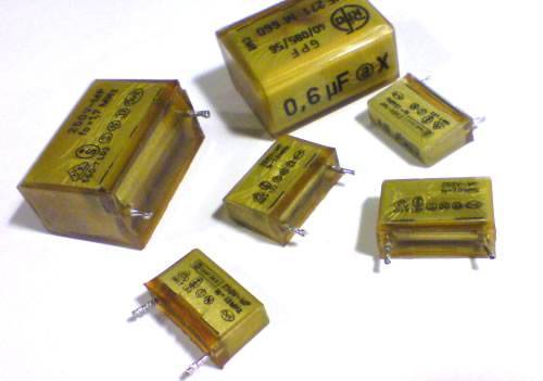
Epoxy Capacitors to be Replaced
- Get new replacements with the same characteristics and pin spacing (0.015 µF Y-type, 0.047 µF X-type and 0.6 µF X-type). The 0.6 µF capacitor can also be replaced by the more common 0.68 µF type. Replace all the epoxy capacitors by soldering.
Note: The same type of epoxy capacitor is installed in the AC line filter module, however, since this module is hermetically boxed (i.e. can't be opened without destroying it), and since (apart from the explosion, a new fuse, and a smell like hell) harm is probably limited, I am not sure whether I should recommend exchanging those capacitors as well. See the remarks towards the AC line filter problem at the end of this chapter.
- It is a good idea to clean all the edge connectors now for a better electrical contact. They are gold-plated, so be careful not to rub the plating off. I recommend using isopropyl alcohol for cleaning. Never use water or any other cleaning agents!
- Re-assemble the PSU, including the aluminium top plate, but do not re-install.
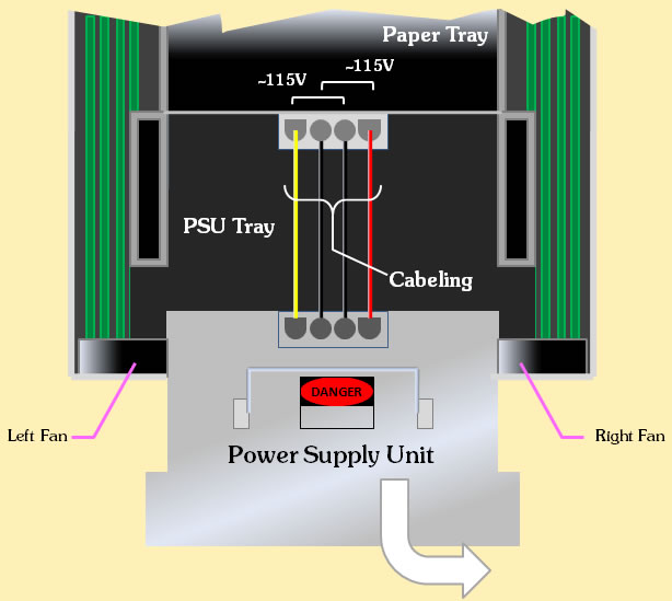
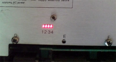
- Connect the mainframe to the power line (still with open cover, and PSU still detached). BE CAREFUL, THERE IS HIGH VOLTAGE ON SOME PARTS! Switch the power switch on. If the fans in the back are running, the first stage of power supply including fuse and line filter seems to be OK. Check the AC voltages at the four-pin-plug as shown in the diagram below with the multimeter to be sure they have both AC 115V (+/- 5%):
- Switch the mainframe off and disconnect from power source.
- Take the MATE-N-LOK or alternatively use the standard PC low-voltage power chord by removing the housings for both the male and the female connector, so you got 4 separate cables. Connect the PSU with the mainframe in the following way:
- Turn the PSU upside down (with the edge connectors up) and connect the light bulbs for dummy load to the 5V and the 12V contacts at the logic voltage sub-assembly (p/n 09845-66583 for option 100 and p/n 09845-66517 for option 200) as shown below:
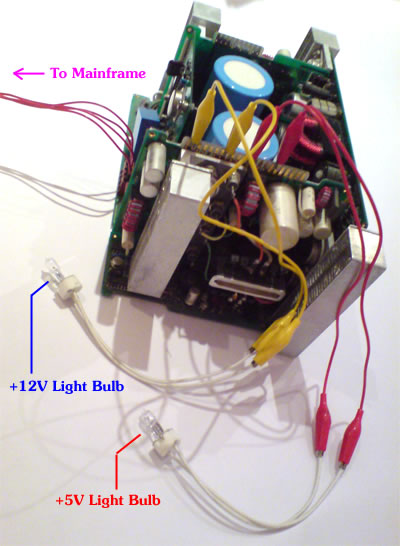
How to Connect the Dummy Load Light Bulbs to the PSU
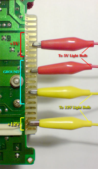
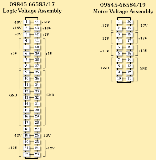
Connection Details for the
09845-66583/17 Logic Voltage Assembly
- Make sure the light bulbs are not defective (check with an Ohm-meter) and double-check the connections.
- Now switch the mainframe on. Now there should be 115V available for the PSU assembly and the light bulbs should burn, indicating there is power on the 5V and 12V circuits. If not, the PSU is probably defective.
WARNING: DO NOT TOUCH THE PSU ASSEMBLY WHEN IT IS CONNECTED TO AC POWER SOURCE. EVEN WHEN DISCONNECTED FROM AC POWER, THE LARGE PSU CAPACITORS KEEP THEIR LOAD WITH UP TO 175V FOR AT LEAST 10 MINUTES. HP'S SERVICE PERSONNEL USED A SPECIAL DISCHARGER BEFORE CONTINUING.
NEVER OPERATE THE PSU OUTSIDE THE MAINFRAME WITHOUT DUMMY LOAD CONNECTED - THIS MAY DESTROY YOUR PSU.
It is always a good idea to check the light bulbs before connecting them to the PSU. If both are defective, there is no dummy load. - Check the DC voltages at the following points against logical GND (they should not differ more than 10%):
- If everything is OK, switch the mainframe off and disconnect it from the power line. Detach all the cables and the bulbs. Still be careful not to touch any blank contacts.
- Wait for at least 30 minutes to give the PSU capacitors a chance to discharge completely. To be sure, check the capacitors charge test points (see the illustration below), they should be in a safe range below 10V.
Your PSU is now ready for operation. Re-install the PSU by plugging it gently into the cage (note the guidings). The PCB connectors must completely fit into the sockets and the top plate should be aligned with the upper side of the cage. Fasten the screws. - Now re-connect the system to the power line and switch it on. If there are test points on the top plate (the newer PSUs do not have test points), use the multimeter with very thin test probes to check DC voltages again against ground (see appropriate tables below for voltage tolerances). If you have an option 200 PSU, there is a voltage-good-indicator with four LEDs, one for each circuit. All four LEDs should be lit.
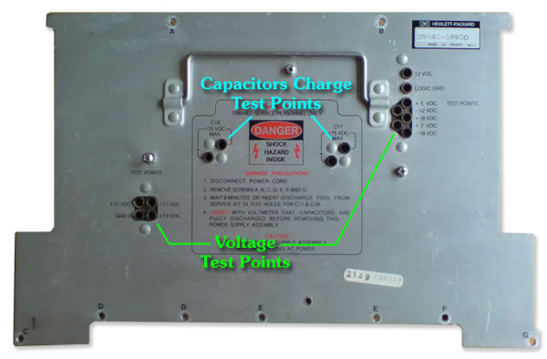
Voltage Test Points (early PSU types only)
9845 Option 100 (Standard) Power Supply SpecificationsVoltage Voltage Tolerance Maximum Current Used By-18V ± 1V .7 amps CRT-17V ± 1V .9 amps Cartridge Drive, Printer Motor-12V ± 5% .85 amps Processors, External I/O, ROM, RAM, Printer, CRT, Keyboard+5V ± 2% 15 amps Processors, External I/O, ROM, RAM, Tape Transport, Printer, CRT, Keyboard+7V ± 5% 1.3 amps Processors, ROM, Printer+12V ± 3% 5.5 amps Processors, External I/O, ROM, RAM, Cartridge Drive, Printer, CRT+13V ± 1V 3.7 amps Printhead, Printer Motor+17V ± 1V .9 amps Cartridge Drive, Printer Motor+18V ± 1V 1.1 amps CRT
- Again, switch the mainframe off and disconnect it from the power line. Re-attach the top cover and install the CRT monitor.
- Now re-connect the system to the AC power source. It is now ready for use and you can switch it on, but don't get panic if it doesn't boot up on the first time. See the Troubleshooting Tutorial if not everything works as expected.
Important note: If you see nothing but a bright horizontal line on the CRT screen, IMMEDIATELY switch the system off!! The CRT is defective and may damage the PSU you just checked.
By the way, there is always a small chance, that a short-circuit in the mainframe or in the CRT may damage your PSU through overloading current, especially with the option 100 PSU types which have no over-current protection like the option 200 PSUs have. But there is no other way to check but powering on and hoping the fuse will blow in-time before the PSU gets damaged.
Bye the way, the normal startup-procedure is as follows:
- One short beep.
- Message "MEMORY TEST IN PROGRESS" on the screen for 10 up to 60 seconds, depending on the amount of R/W memory installed.
- Message "9845 READY FOR USE." with blinking cursor.
- Congratulations, most of the vintage 9845 systems won't get that far :-)
The Model 200 PSU
The model 200 PSU is different towards the standard PSU. It has been designed for higher currents, since power has to be supplied to the 98780A enhanced monitor and the bit slice LPU. HP's engineers again made it double well and not only built a PSU with higher load capacity, but also spent some circuits for monitoring the power output characteristics like current and voltage.
The monitoring results are shown via four power-good LED indicators, which replace several testing points of the older PSU types. All four LEDs should be lit.
Power Good LEDs (option 200 PSUs only)
I am not sure whether those model 200 PSUs need a dummy load to be tested, however if they need this dummy load, it probably has to be a bit higher than for the standard PSUs in addition to the rest of the system. I have not yet figured out which outputs should be covered and how much load should be applied.
Thanks to the over current and over voltage circuits, those PSUs are safer than the standard types anyway. Note that there is still one of those epoxy capacitors installed in the PSU, which MUST BE EXCHANGED BEFORE TURNING ON THE SYSTEM!!
Now, for the sake of completion, here is the data for the modell 200 PSU's outputs:
9845 Option 200 Power Supply Specifications |
|||
| Voltage | Voltage Tolerance | Maximum Current | Used By |
| -18V | + .9V / -5V | .8 amps | CRT |
| -17V | ± 2V | 1.5 amps | Cartridge Drive, Printer Motor |
| -12V | ± .6V | 1.0 amps | Processors, External I/O, ROM, RAM, Printer, CRT, Keyboard |
| +5V | + .35V / -.05V | 30 amps | Logic |
| +7V | ± .3V | 1.5 amps | Processors, ROM, Printer |
| +12V | ± .6V | 6.8 amps | Processors, External I/O, ROM, RAM, Cartridge Drive, Printer, CRT |
| +13V | ± 1V | 4.9 amps | Printhead, Printer Motor |
| +17V | ± 2V | 1.5 amps | Cartridge Drive, Printer Motor |
| +18V | + 5V / - .9V | 1.8 amps | CRT |
The pinout of the output edge connectors is the same as for the standard PSUs.
The AC Line Filter Problem
As mentioned above, the epoxy capacitors used in many of vintage HP products mainly for interference suppression are not only installed in the PSU's, but also in the AC line filter (see the photo at the beginning of the page). This filter is completely encapsulated in a hermetically sealed box, which can be found at the rear of the system (the AC power jack is part of this module). The module contains just a power resistor, a coil, and a couple of those time-bombing epoxy capacitors.
The one bad part is that this module is normally always connected to the power line, so it can happen any time that this module gets blasted, even when the system is completely switched off. The other bad part is that fixing those capacitors isn't easy since they are encapsulated in a metal box which can't be easily opened. The good part, however, is that harm towards the rest of the system in general is limited. What will happen is that your home's fuse gets blown and the room where it happended can't be used for the next 24 hours (good ventilation assumed).
Now, if the AC line filter gets blasted, you need a replacement. Either an identical module with the same size & characteristics, or, and this is the ugly part, you'll have to open and clean the module and then to exchange those capacitors against new ones.
Before you get access to the line filter module, you'll have to remove the rear panel with the fans (simply remove the four screws at the rear at the buttom side of the main frame). When unsoldering the three cables which lead to the system, remember which cable was at which soldering terminal.
If you decide to exchange the capacitors (either before or after the explosion), you'll need to cut the metal box open e.g. with a dremel tool. Here is where the cuts should be done:
Where to Dremel the Line Filter in Order to Open the Box
Take care not to cut too deep in order not to destroy the components within the liner filter module. If cleaning is necessary, I recommend using isopropyl alcohol. Use a soldering iron with some soldering paste to get the old capacitors off the PCB and replace with new capacitors. There is some insulating foil which separates the box from the components, I recommend replacing this, too (I like flame resistant hard paper better than plastics, but at least it is a matter of taste), since you won't be able to keep it undamaged.
Once repaired, you can try to re-solder together the box parts, or simply fix them together with some insulation tape.