The 9845 Displays
At design time of the 9845 series, CRT displays already had been very common for terminals which were connected to mainframes and mini computers. The CRTs used in those terminals differed from TV CRTs in many aspects. They offered in general a much higher resolution (i.e. video bandwith) and used a phosphor with high latency for avoiding early eye fatigue. TVs on the other side needed low latencies for fast screen movements and could only support a limited video bandwidth throught the whole signal stream, resulting in a diffuse image with high flicker. Finally, TVs used a color signal modulation scheme which could not even rudimentary guarantee the desired color ('NTSC = Never The Same Color') and used just half the horizontal resolution of the luminance signal. So using TV CRTs for computer systems can be considered as a low cost solution for home computers, where a professional display was not affordable. Most home computers were restricted to a 40 by 25 characters display, mainly due to the limited video bandwith.
9845 Displays - From Left to Right: 98750A, 98780A and 98770A
Professional terminals, on the other side, although optimized for text interaction (like the HP 2540, the DEC VT52 or the IBM 3270) and partly graphics (like the Tektronix 4014), were in fact descendants of another very early type of I/O interface device, the teleprinter (TTY). Terminals therefore used a very low speed line for communication with the host, which again was not adaquate for real-time interactive graphics as needed for a workstation.
So HP's engineers developed a solution which appeared much more like a display processor than like a plain CRT display. HP's engineers talked about those displays simply as 'tops', but in fact they designed everything at its best. With the knowledge of the terminal designs, they chose a phosphor with high latency and a 60 Hz refresh independent of the power line frequency. They decided to leave the digital path as late as possible in order not to degrade the signal quality (as it is done today with DVI or HDMI) and used high-quality components and complex adjustments for the video circuits, which results in superior image quality, even after now more than 30 years. They selected a 9 x 15 pixel character cell to display all ascenders and descenders without compromise. They designed dedicated, high bandwidth digital interfaces for text and graphics data between main system and display unit. And they used hardware accelerated vector generators for the more advanced 9845B model 200 and 9845C display systems.
The decision to combine the display unit directly with the main system makes monitor positioning a bit less flexible compared to a standard PC (monitor position is fixed). Moreover, the connection interface is completely proprietary, so it isn't possible to connect anything but an HP 9845 display unit. All video signals are generated inside the monitor, the interface to the computer is completely digital, comparable to DVI in contrast to VGA.
In general, HP offered four displays or 'tops' for the 9845 series: the 98750A standard monochrome display with 12" tube and optional graphics (code name 'Cyclops') for the standard 9845A/B, a very similar design for the 9835A, and two high-performance display units, the 98780A enhanced monochrome display (code name 'Aurora') with 12" tube for the 9845B model 200 and the 14" 98770A color display (code name 'Odyssey') for the 9845C. One of those display units was required, but other displays types like RGB monitors (via RGB interface) or vector displays (via HP-IB connection) could be connected as secondary units.
In fact, the advanced display systems were much more than simple CRT monitors. They were highly complex computing devices with memory, processors, vector generators and light pen logic. The increased power requirements were met by an enhanced mainframe model 200 power supply (for the 98780A) or a separate built-in PSU unit (98770A). Both monitors also served with small modifications as advanced display options for the HP 9000 series 500 computers.
Common Features
Alpha mode and graphics mode can be enabled at the same time only with the 98780A enhanced monochrome display or the 98770A color display, not with the 98750A standard display.
The whole system was quite sophisticated for the time, and flexible enough to support different types of monitors through the same connection (98750A standard monochrome, 98780A enhanced monochrome, 98770A color monitor). The enhanced and the color monitors had a very special feature, a vector generation hardware. The vector engine was built for the 98770A by a bit-slice processor - a quite popular type of implementation for hardware accelerated graphics, and for the later 98780A with a custom chip.
The 98750A standard monitor required an optional graphics module for graphics capability. The 98770A color monitor was a bit delicate, it had its own highly complex PSU and color convergence had to be adjusted via 39 (!) potentiometers. Both the 98780A enhanced monochrome monitor and the 98770A color monitor had integrated soft-keys and could be equipped with light-pen logic. Both the soft-keys and the light-pen could be traced with additional commands via the IOD interface. Today the 98770A monitors, if your're lucky enough to acquire one, mostly suffer from a defective PSU (which was even more complex than the one for the option 200 mainframes).
In principle, all monitors are electrically compatible with all mainframes, except that some specialities of a monitor might not be used accordingly due to different display firmware. However the mechanical layout of the standard monitor leg is a bit different to that of the 98770A and the 98780A, so that it is mechanically not possible to connect a 98770A or 98780A to a standard mainframe, and you actually better should not try to do so, since the 98780A will take too much power from the standard PSU (the 98780A is intended to operate in combination with the enhanced option 200 PSU).
In principle, the alpha control assembly should be the one that suits to the monitor, especially for driving the graphics and alpha enable signals. Another point is that the Color and Enhanced Graphics option ROMs assume the refresh memory at the address 60000, not at 70000, which must also match with the appropriate type of alpha control assembly. However, I've never tried, and I'll probably never do (those instruments are too valuable for me to do such kind of testing).
The 9845 mainframe senses the presence of a monitor through the vertical retrace signal, which is passed through the monitor connectors to the processors (DC/ flag for the 9845A and HLT/ flag for the 9845B/C). Once this signal is missing, the mainframe won't start up correctly (instead a repeated beeping sound is generated).
The complete display system for all 9845 systems consists of four parts:
- the alpha memory buffer,
- an alpha control assembly,
- a graphics subsystem and
- a CRT monitor system.
All display systems can operate in two modes, the alpha mode and the graphics mode. Whereas the standard display can only show either text or graphics at one time, the advanced displays are capable of showing both alpha and graphics data simultaneously. Alpha and graphics data cover different areas of the screen. Simply said, the text data ratio is widescreen (1:1.71) and the graphics data is more like 4:3 (actually 1:1.23).
The following secstions give an overview over the basic concepts common to all display types.
The Alpha Display
In alpha mode, all display information is stored as characters in the alpha memory buffer, a part of the PPU R/W memory. The buffer can be directly written both by the PPU and the LPU. Any display operation in alpha mode is done by just writing to the alpha memory buffer, which is located in the PPU R/W memory block 1 at octal address 70000 for the standard display and 60000 for enhanced monochrome and color displays. The alpha display controller reads out the alpha memory buffer 60 times in a second.
The 98750A standard monochrome, the 98780A enhanced monochrome and the 98770A color display all interpret the data from the alpha memory buffer in a different way. Consequently, there are different assemblies for processing the data from the alpha memory buffer (A3 09845-66503 for the 98750A and A34 98770-66534 for the 98770A and the 98780A).
Standard Display (98750A Monitor with A3 Assembly)
For the 98750A, all bits but the MSB of the very first word in the alpha memory buffer at address octal 70000 build the complement of the address where to start processing the next word (normally, this is address octal 70001). The MSB tells whether to switch to graphics mode (bit 15=0) or to alpha mode (bit 15=1). Consequently, the display can not enable both graphics and alpha mode at the same time.
This feature enables a "windowing" capability: Since an efficiently managed refresh buffer can store much more content than a display can hold, a text window can be used to move along the buffer (including scrolling) without the need to re-write the display data, just by re-positioning the pointer at 70000.
The character information is held in the alpha memory buffer as 8-bit data. Each byte can be either character data or control information, so that a 16-bit word can hold two characters. If the MSB of a byte is clear, the byte describes a character to be displayed, and the remaining bits correspond to the characters ASCII value. If the MSB is set, bit 6 determines whether the data describes a feature set/clear operation (bit 6=0) or a flow control command (bit 6=1):
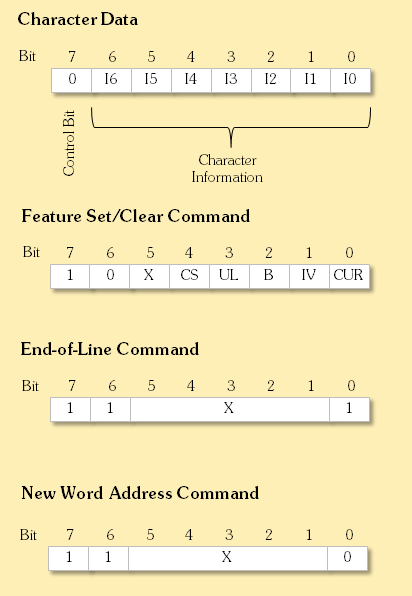
where an X designates arbitrary contents and
| I0..I6 | ASCII character code between 0 and 127 |
| CS | Character set select: 0 = standard set, 1 = foreign characters |
| CUR | Cursor |
| IV | Inverse video |
| B | Blinking |
| UL | Underline |
A text feature is set with a 1 in the appropriate bit, and cleared with a 0 in this bit.The feature information is latched and therefore valid for all following characters.
The End-of-Line command simply tells the display to position the next character at the beginning of the next line.
The word following a New Word Address command is interpreted as the complement of the address for the next data word to be processed. This feature can be used to skip portions of the buffer memory (or even loop through the buffer memory).
98780A Enhanced Monochrome/98770A Color Display with A34 Assembly
For both the 98780A and the 98770A, the character information is decoded and transferred by the A34 assembly as 16-bit data (8-bit character information, and 7-bit attribute information plus one control bit) via the connector in the left monitor leg to the CRT monitor circuits with the required timing. The CRT monitor circuit takes the data from the alpha control assembly and converts those information with the help of a character ROM to compose the current scanline (each character provides 9 horizontal pixels to a scanline).
Each character is made up of the following bits:
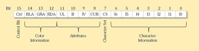
where
| I0..I6 | ASCII character code between 0 and 127 |
| CS | Character set select: 0 = standard set, 1 = foreign characters |
| CUR | Cursor |
| IV | Inverse video |
| B | Blinking |
| UL | Underline |
| RDA | Red color (98770A only) |
| GRA | Green color (98770A only) |
| BLA | Blue color (98770A only) |
| Ctrl | Control bit |
When set, the control bit instructs the alpha logic to process the data word not as character but as command (similar to a display list). There are three commands:
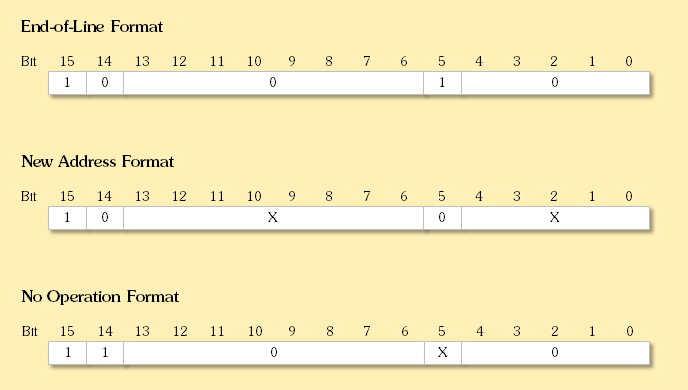
where an X designates arbitrary contents.
The End-of-Line command is intended for efficient use of the refresh buffer. When a "character" word of this format is read, the next character word is assumed to be at the beginning of the next line (same as CR/LF).
The New Word Address command is used to re-position the character pointer to another memory address. When a "character" word in this format is read, the next character word is assumed as the new memory address. This feature can be used to skip portions of the buffer memory (or even loop through the buffer memory).
The No Operation command specifies that the character word should be ignored.
As with the address octal 70000, the first word at address 60000 for the 98770A and the 98780A has a special meaning. For the 98770A or the 98780A monitor, bit 15 switches the graphics mode on, and bit 14 the alpha mode (so both modes can be operated in parallel). The remaining 14 bits specifiy the first address of the next character word.
Character Generation
The CRT unit takes over the attributed character information and generates characters from a character ROM on the scanlines of the display. The alpha display provides 25 lines of 80 characters each on a 720 x 375 dot raster for the 98750A display and 28 lines of 80 characters each on a 720 x 420 dot raster for the 98770A and the 98780A displays.
Normally, the 9845 alpha display is split into several areas:
- The print area, where all output of the BASIC PRINT statement is displayed. The print area uses 20 lines.
- One unused line as separator between print area and the display line,
- the display line, where all output of the BASIC DISP statement is shown
- two lines for user input (keyboard entry area), and
- one line for system messages, including the "run light" for indicating system activity.
The 98770A and 98780A displays add three more lines:
- Another unused line as separator between the system message line and the soft-key labels, and
- two lines for the soft-key labels, defined with the BASIC LABEL KEY# or LABEL KEYS statements.
However, this separation is specific for BASIC programs and has nothing to do with the underlaying alpha control logic, except that a split alpha display including separate scroll areas is easy to implement by using the New Word Address alpha logic command. Programs not implemented in BASIC can easily overcome this artificial restriction.
The Graphics Display
The graphics subsystem is placed inside the monitor and directly connected to the IOD bus through a connector in the right monitor leg. The graphics subsystem is controlled by a seqence of commands, which are sent to the graphics system from the PPU via the IOD peripheral bus.
For the graphics hardware, the following commands are supported:
| Graphics Primitive |
Mnemonic | Attributes | Parameters | Operation | Opcode (octal) | ||
| Standard | Enhanced Monochrome |
Color | |||||
| write pixel | INT, DMA | word address, bit address, value | Writing individual pixels |
11 | n/a | n/a | |
| write words | MWC | INT, DMA | word address (standard only), data | Writing full words |
10 | 10 | 00 |
| read words | MRC | INT, DMA | word address (standard only), data | Reading full words |
14 | 11 | 01 |
| load x cursor | LXC | n/a | X coordinate, cursor type | X cursor position |
04 | 17 | 17 |
| load y cursor | LYC | n/a | Y coordinate, cursor color | Y cursor position |
n/a | 16 | 16 |
| load y cursor | LYC | n/a | Y coordinate | Y cursor position (small blinking) |
00 | n/a | n/a |
| load y cursor | LYC | n/a | Y coordinate | Y cursor position (full-screen) |
01 | n/a | n/a |
| load y cursor | LYC | n/a | Y coordinate | Y cursor position (small horizontal) |
02 | n/a | n/a |
| set line type/area fill | SLT | INT, DMA | repeat factor, line type/area fill select, line type/area fill pattern | Setting line types |
n/a | 06 | 13 |
| load memory control | SMC | INT, DMA | dominance, erase/write, enable | Loading memory control |
n/a | 12 | 12 |
| load end points | LEP | INT, DMA | move/draw, end point[, rubber band*] | Specifying end points for drawing vectors and area fill |
n/a | 01 | 15 |
| load arc | LARC | INT, DMA | move/draw, end point[, rubber band*] | Specifying end points for drawing arcs |
n/a | ? | n/a |
| load I/O address | LIO | INT | increment, y line address, increment, x pixel address | Loading (X,Y) I/O address |
n/a | 07 | n/a |
| load X I/O address | LXA | INT, DMA | word address | Loading X I/O address |
n/a | n/a | 10 |
| load Y I/O address | LYA | INT, DMA | word address | Loading Y I/O address |
n/a | n/a | 11 |
| clear words | INT, DMA | word address, dummy data | Clearing full words |
12 | n/a | n/a | |
| erase | INT | fast clear | Filling and clearing the full screen during a single scan cycle |
n/a | 15 | n/a | |
| clear/set words | INT, DMA | dummy data | Clearing and setting full words |
n/a | n/a | 02 | |
| load color mask | INT, DMA | color mask | Loading color mask |
n/a | n/a | 04 | |
| load scan | LSCAN | INT, DMA | start pixel address x,y | Specifying start of display |
n/a | ? | n/a |
| video | INT, DMA | on/off | Switch video display on/off |
n/a | 13 | n/a | |
* A special feature is the rubber band/drag function. The idea behind is to provide means for lines which are drawn without destroying the current background image, similar to the Sprites concept. However, the overlay isn't built from a bitmap but from an arbitrary vector object. Rubber band is a line with a fixed start point and a moveable end point (ideally in combination with a light-pen or graphics tablet device). The mechanism works with multi-vector objects and can be used to move ("drag") even more complex objects in non-destructive manner over the screen. So this feature can be used to implement drag-and-drop funtionalities for graphical user interfaces.
The feature is implemented in hardware for the 98780A enhanced monochrome display only and can support objects with up to 4094 pixels, which is more than enough to implement a full-screen selection-type square rubber band. There is a software emulation for the rubber band feature (without support for multi-line objects) for the 98770A color display requiring either a special binary routine (RUBBND) or an Enhanced Graphics option ROM.
Most graphics primitives consist of a command part with following graphics data, e.g. a "write pixel" command with a following list of pixel coordinates. In general, the PPU first allocates a memory buffer in its R/W memory, writes all the pixel coordinates into that buffer and then sends the "write pixel" command via IOD bus to the graphics subsystem, ideally with DMA enabled. The graphics system then fetches all the pixel data from the buffer and sets the graphics pixels accordingly while the PPU may already fill another buffer with new pixel data.
The graphics display uses a different part of the screen. The alpha display is optimized for using the full horizontal width, whereas the graphics display area should use as much of the whole display as possible without too much distortion. So for graphics a modified raster of 560 x 455 pixels is used.
The graphics memory is located inside the display unit and can be accessed via one of the graphics primitives. For the 98750A standard display, all pixel data is written with "write pixel" command. The 98770A and 98780A displays offer more sophisticated vector drawing commands, which speeds up graphics by a factor of 50. Alternatively, for all displays the graphics memory can be more directly accessed via the "read word" and "write word" primitives, again ideally with DMA activated. This is the way how screendumps are generated. Unfortunately, the vector engines in the 98770A and 98780A can be active only during the retrace phases, when the graphics buffers are available for writing. Modern systems would use dual-ported RAM or double-buffering, both techniques which probably would have been too expensive for the 9845. Disabling the display during writes would give longer write periods, but is not possible since the DRAM refresh is performed with scanning the memory.
All graphics pixels are represented as bits in a 16 kWord graphics buffer. Each graphics line is made up of 560 bits or 35 words. Color information in the 98770A is done by combining three separate buffers (memory planes). So each pixel consists of three bits which can select one of eight possible colors. Each memory plane can be freely assigned to any of the eight primary colors (black, red, green, blue, magenta, cyan, yellow and white) via a look-up-register, the so-called "musical memories". The color information of each memory plane is triggered by the particular bit in each memory plane, and the color information of each plane is or'ed to the final color (see the 9845C section for details).
98750A Close Up
 |
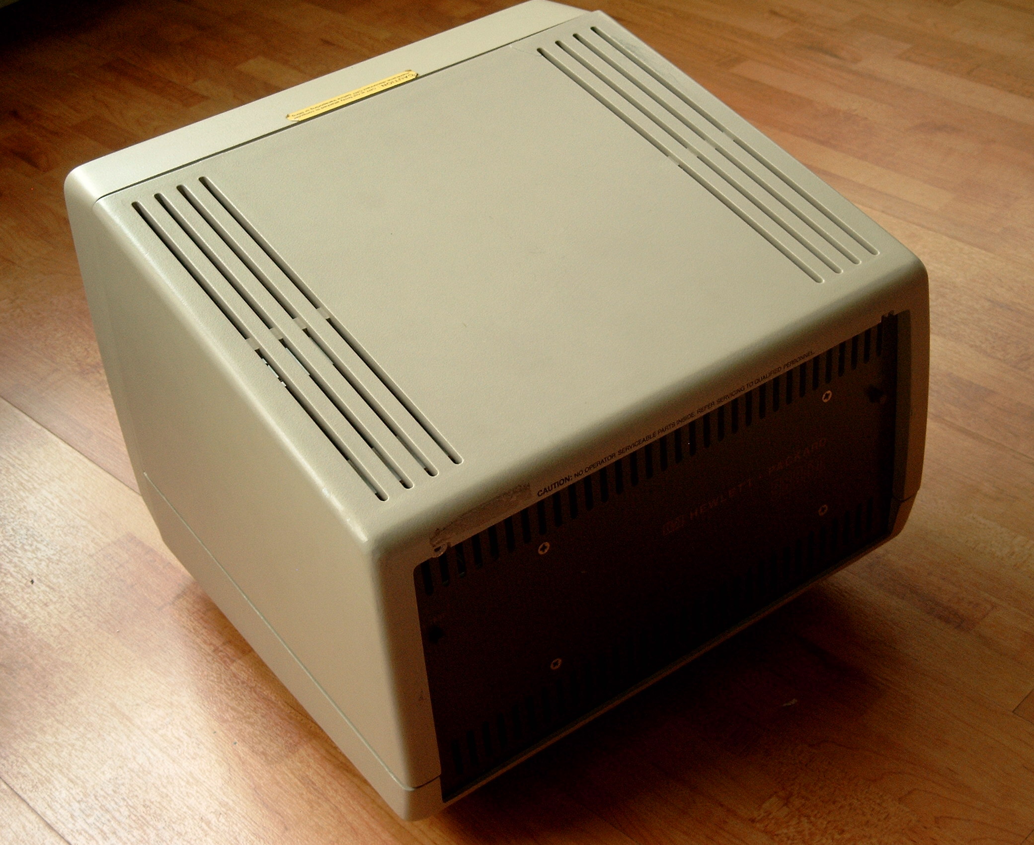
The standard 9845 monochrome (green) monitor. |
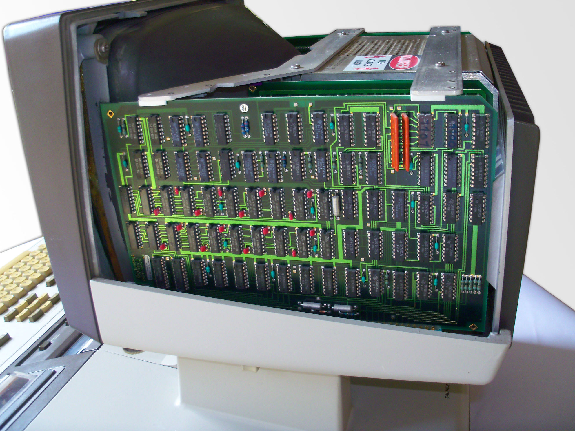 |
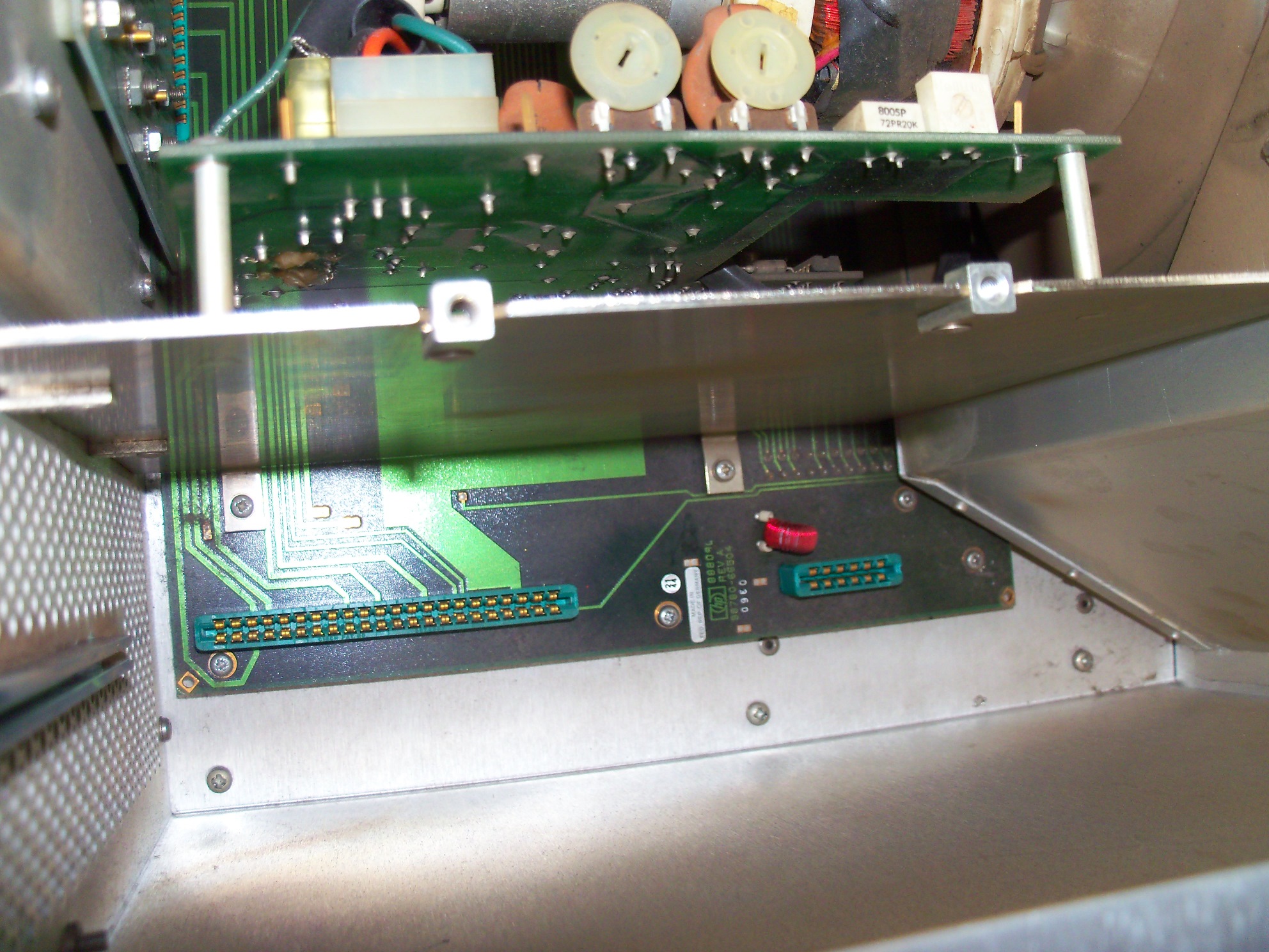
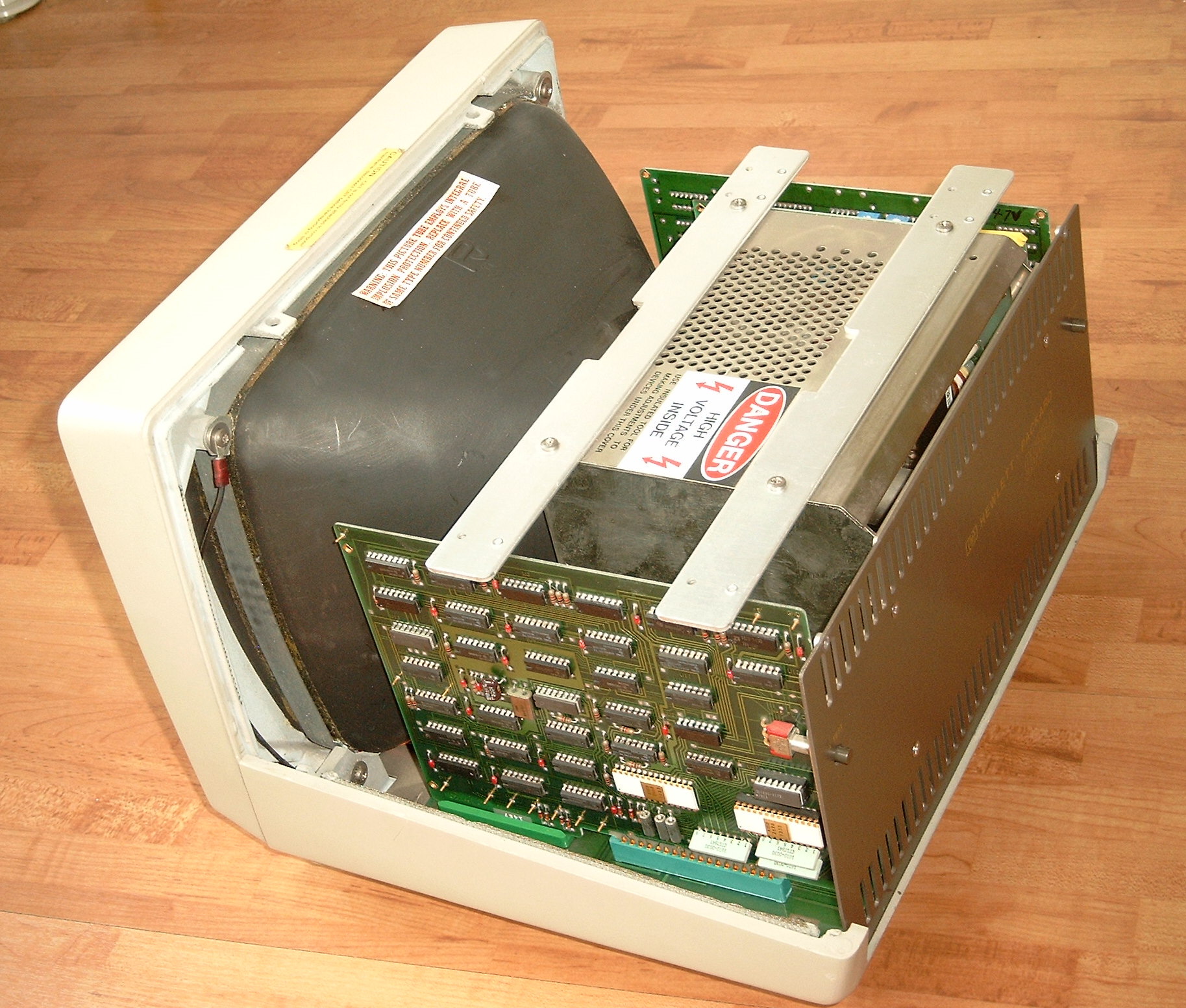
With the top cover removed, access is provided to the assemblies inside the monitor. The two board on the right side belong to the optional graphics subsystem. Here the graphics memory board is shown. It features 16 kBytes of bitmap memory. |
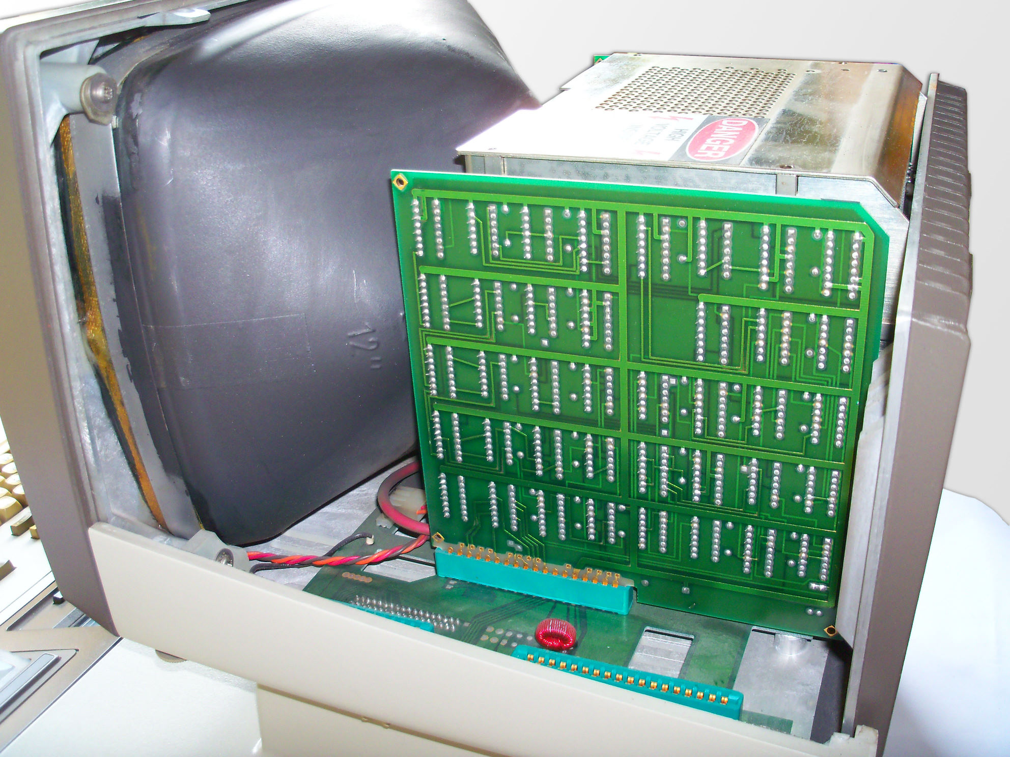 |
Behind the memory board is the graphics controller or graphics scanner. Its role is to communicate with the mainframe via the system I/O bus, which is routed to the display through the right monitor leg, to generate the graphics cursor and to provide access to the bitmap memory.
|
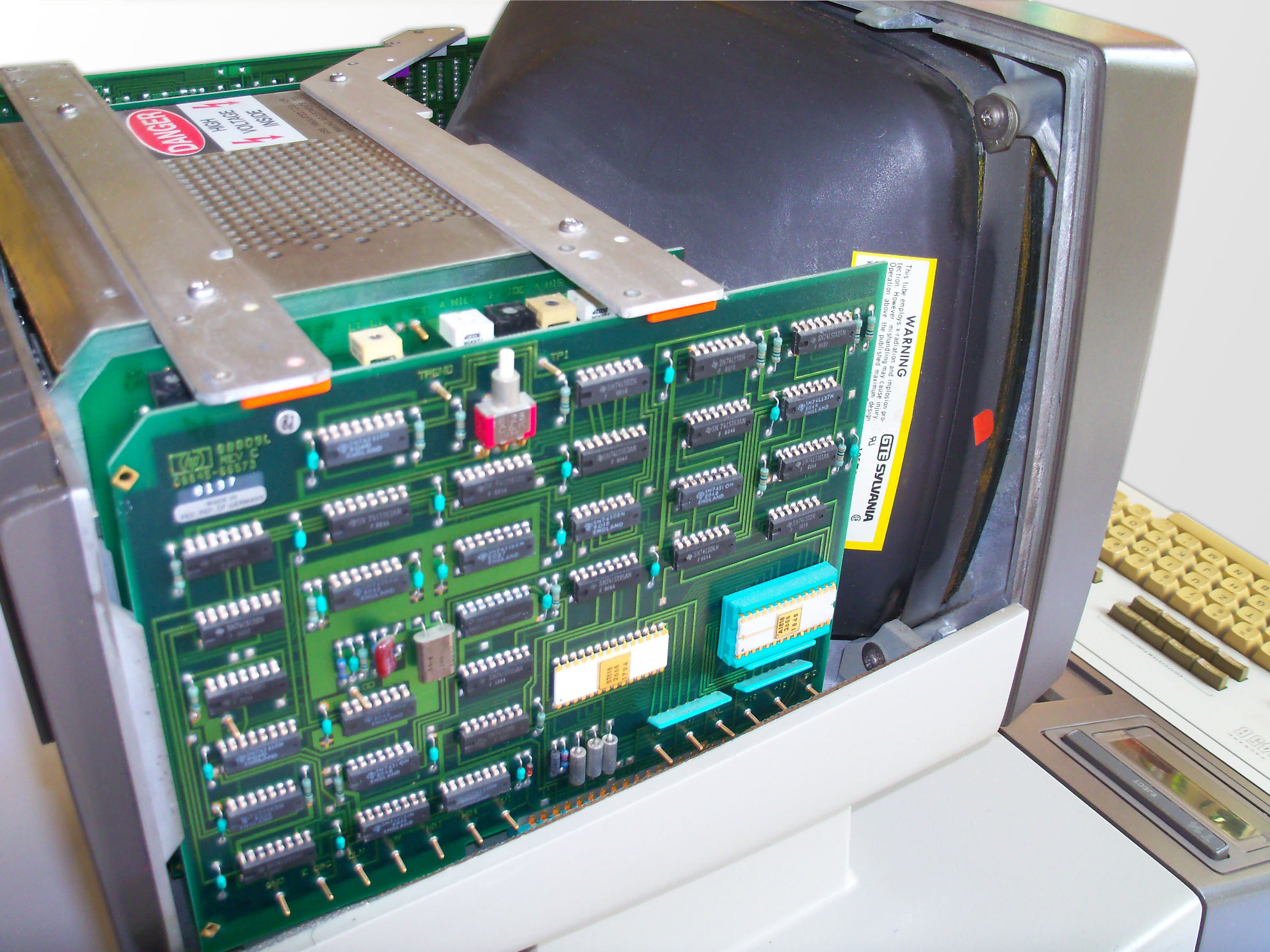 |
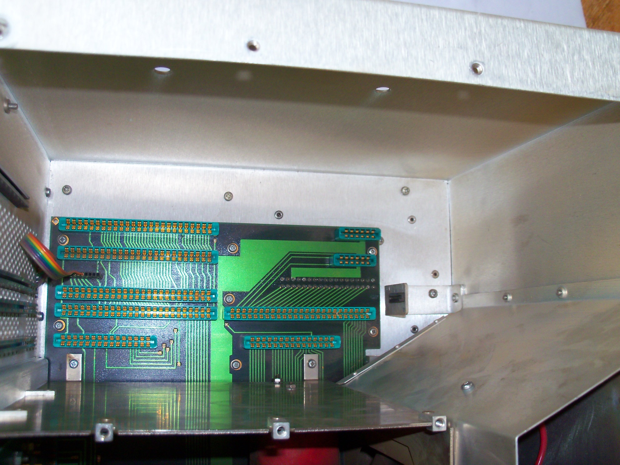
On the other side of the monitor, the display logic board provides all the circuits necessary for generating characters on the display. The board is also responsible for implementing text attributes (blinking, underline, inverse). The display logic board connects to the alpha control assembly through the left monitor leg, from where the character data is streamed together with the attribute information. Note the test button, which simply generates an inverse display, and the white ROM ICs holding the character information for the primary and the alternate character set. |
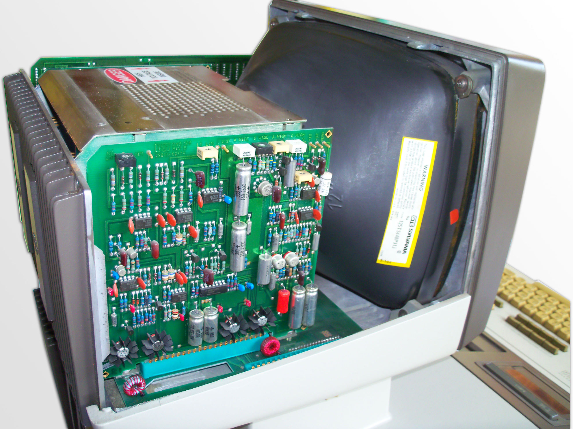 |
Behind the display logic is the analog board, where the control signals for the CRT are shaped to the proper display dimensions. |
 |
The high voltage driver regulators are mounted at the back of the monitor towards a heat sink with cooling fins. |
 |
The high voltage driver board directly controls the CRT tube/yoke assembly. |
98770A Close Up
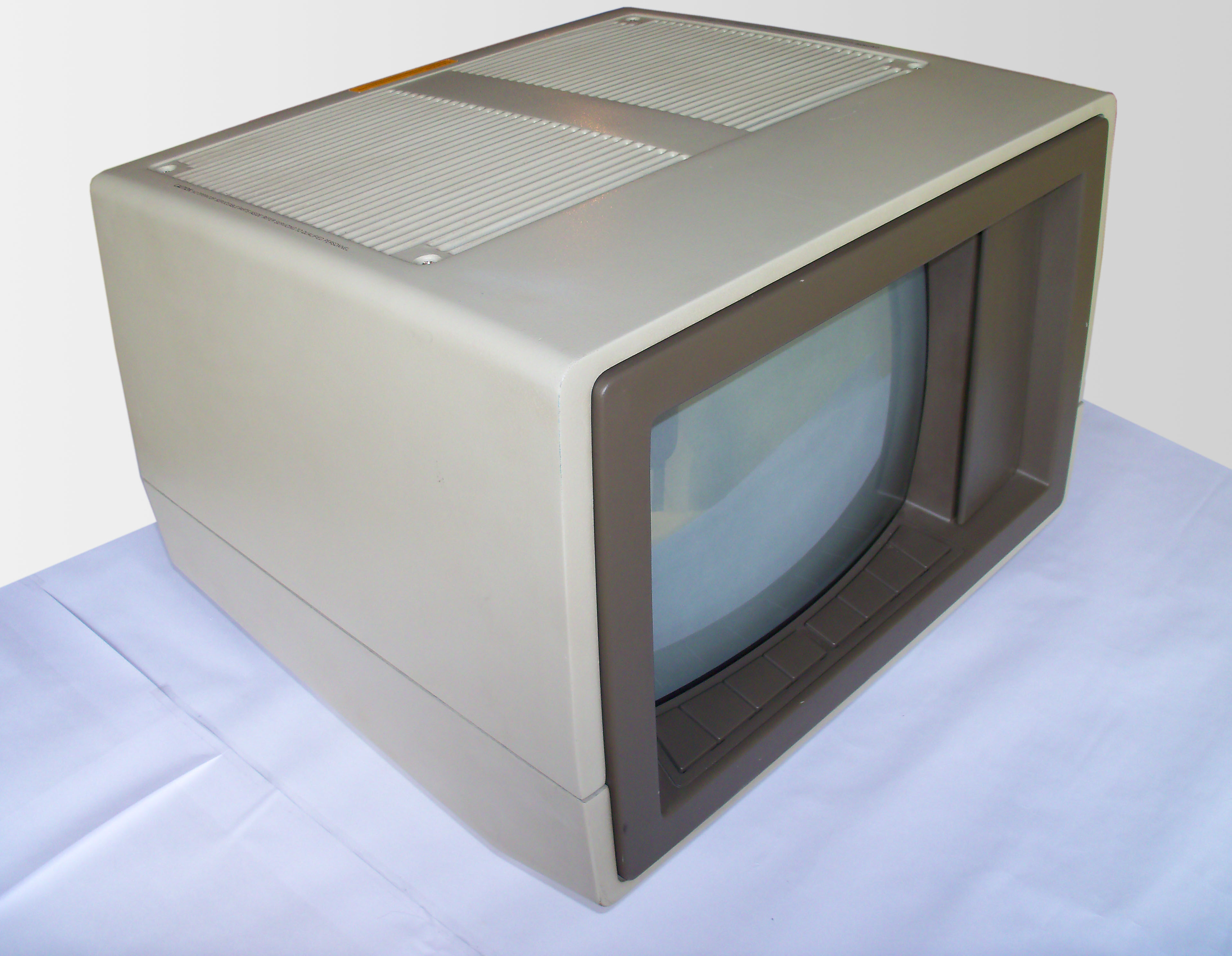 |
The (ultra rare) 98770A color display for the 9845C. |
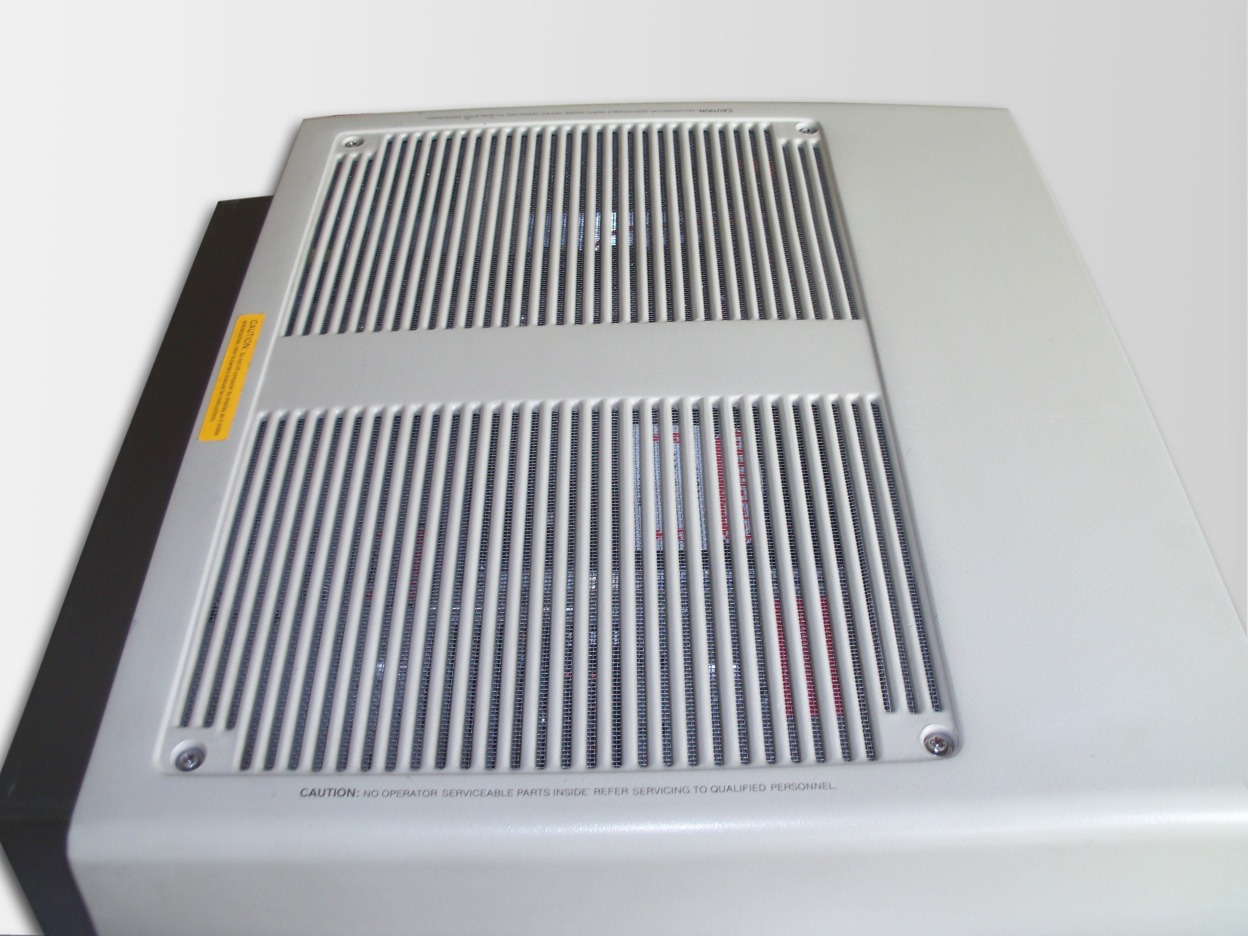 |
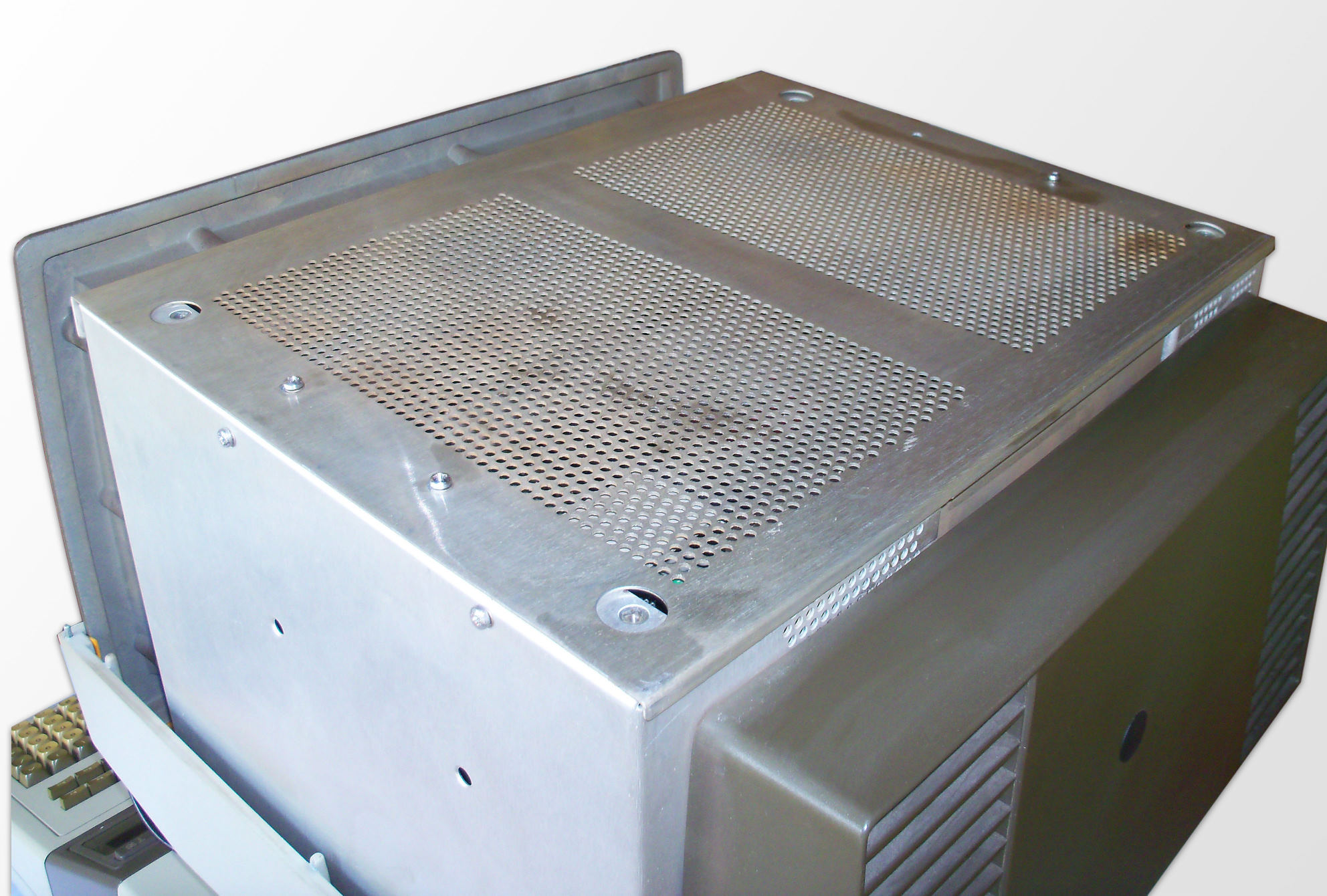
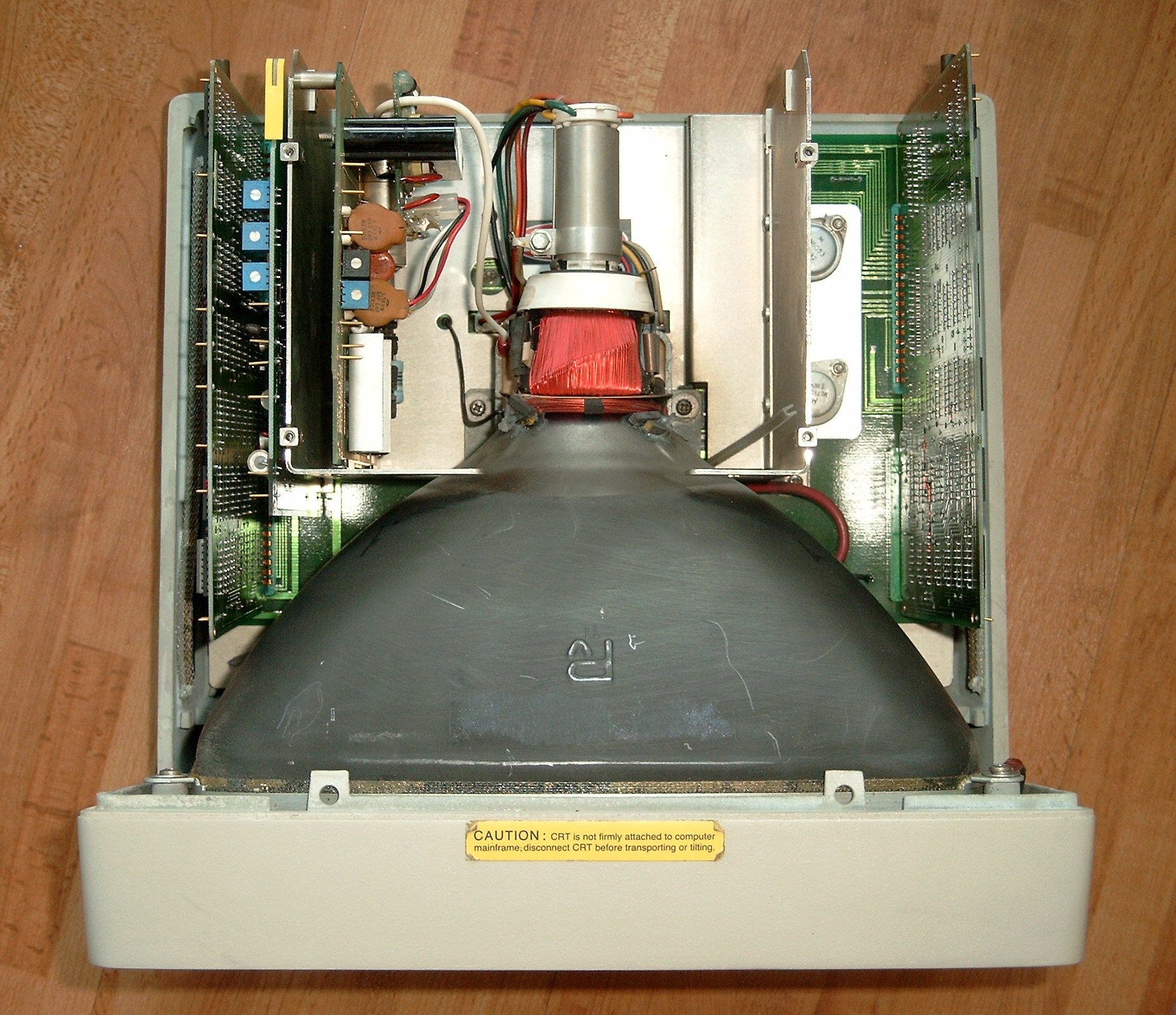
Top view of the 98770A. Note that the rear left screw (lower left screw on this picture) is special in that it is exactly above one of the large capacitors and therefore shorter than the others in order not to perforate the capacitor. Actually, a small flaw in monitor hardware design. Take this into account when re-assembling the cover. Newer models keep that screw so it doesn't fall off when unfastened. |
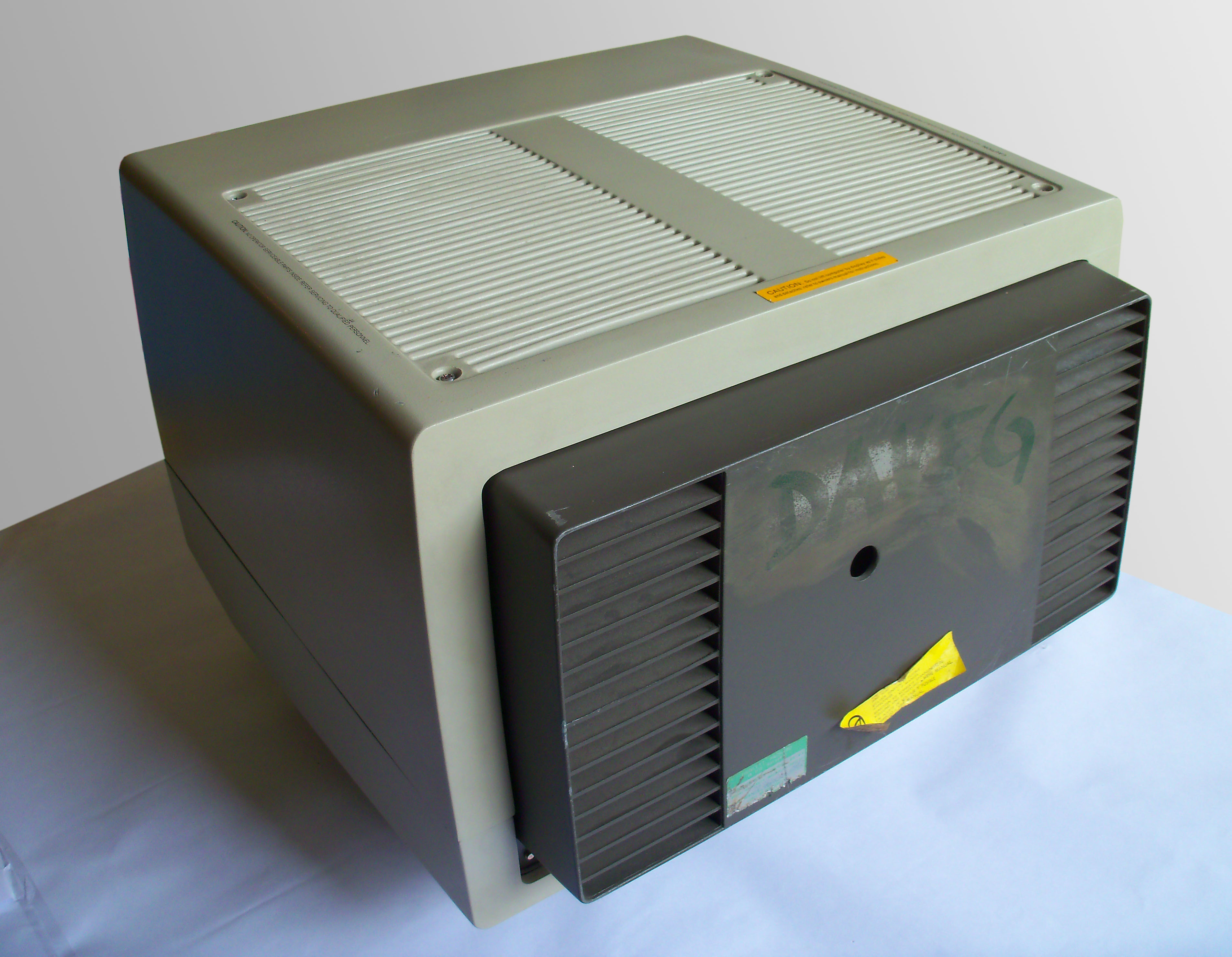 |
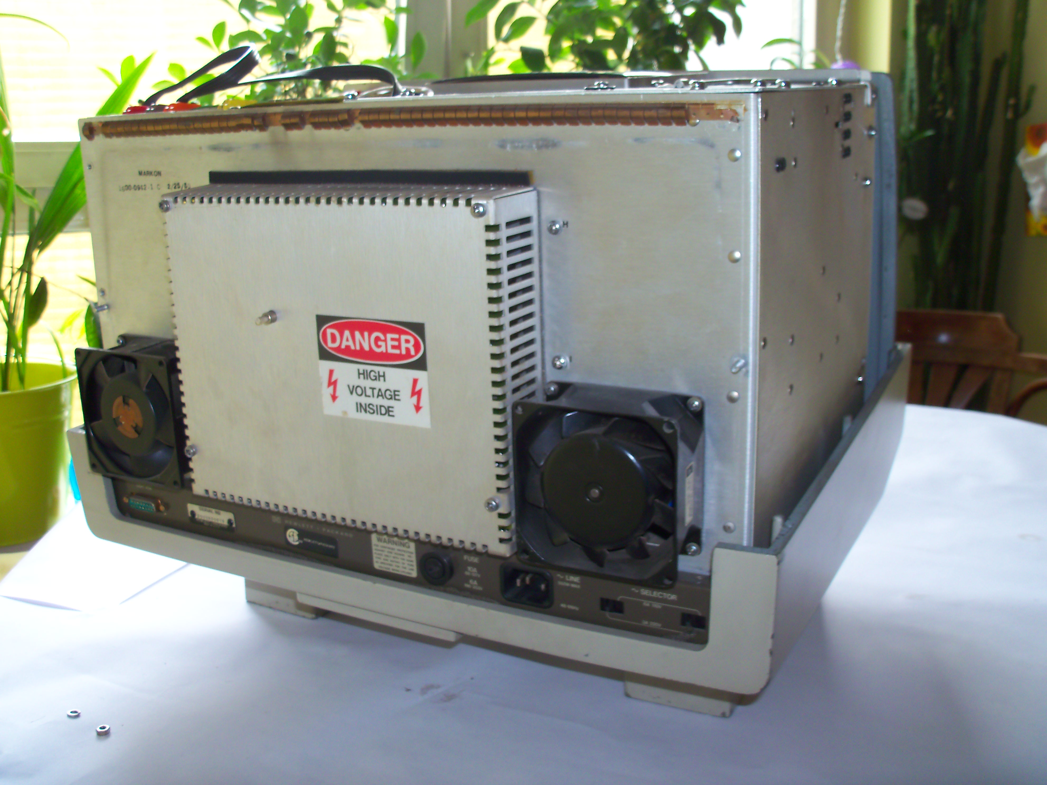
The monitor case looks very much alike that of the 98780A, with some minor changes (shielding integrated in the monitor cover, fans for active cooling, front door above convergence controls). |
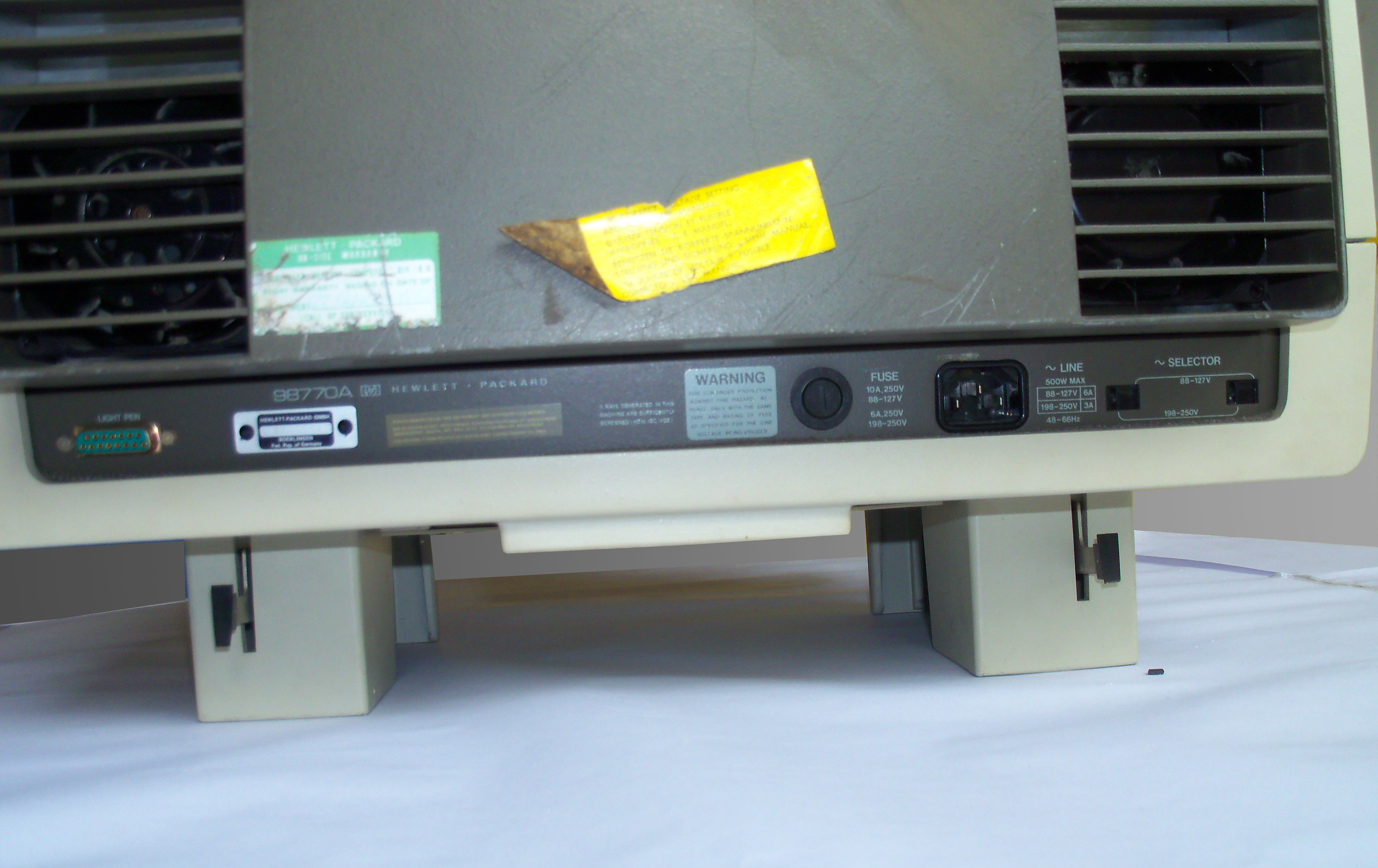 |
See the light pen connector, the serial number plate, the fuse (10 amperes for 110V, 6 amperes for 220V), and the power line jack. The 98770A was specified for up to 500 watts power consumption. |
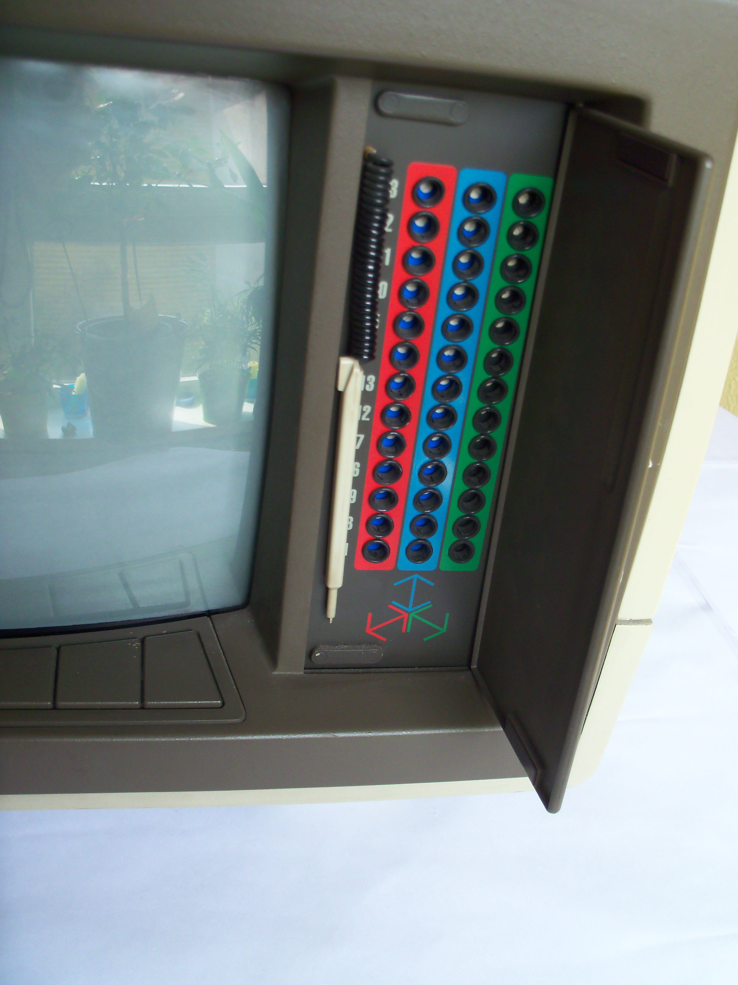 |
Convergence on a complex color monitor like the 98770A can be a problem. Once convergence is adjusted ok in the upper left corner of the screen, it may be bad on the lower right corner etc. So there are 13 (!) convergence adjustment points to get a good convergence over the whole screen. Each convergence adjustment has a dedicated potentiometer for each of the primary colors red, blue and green. |
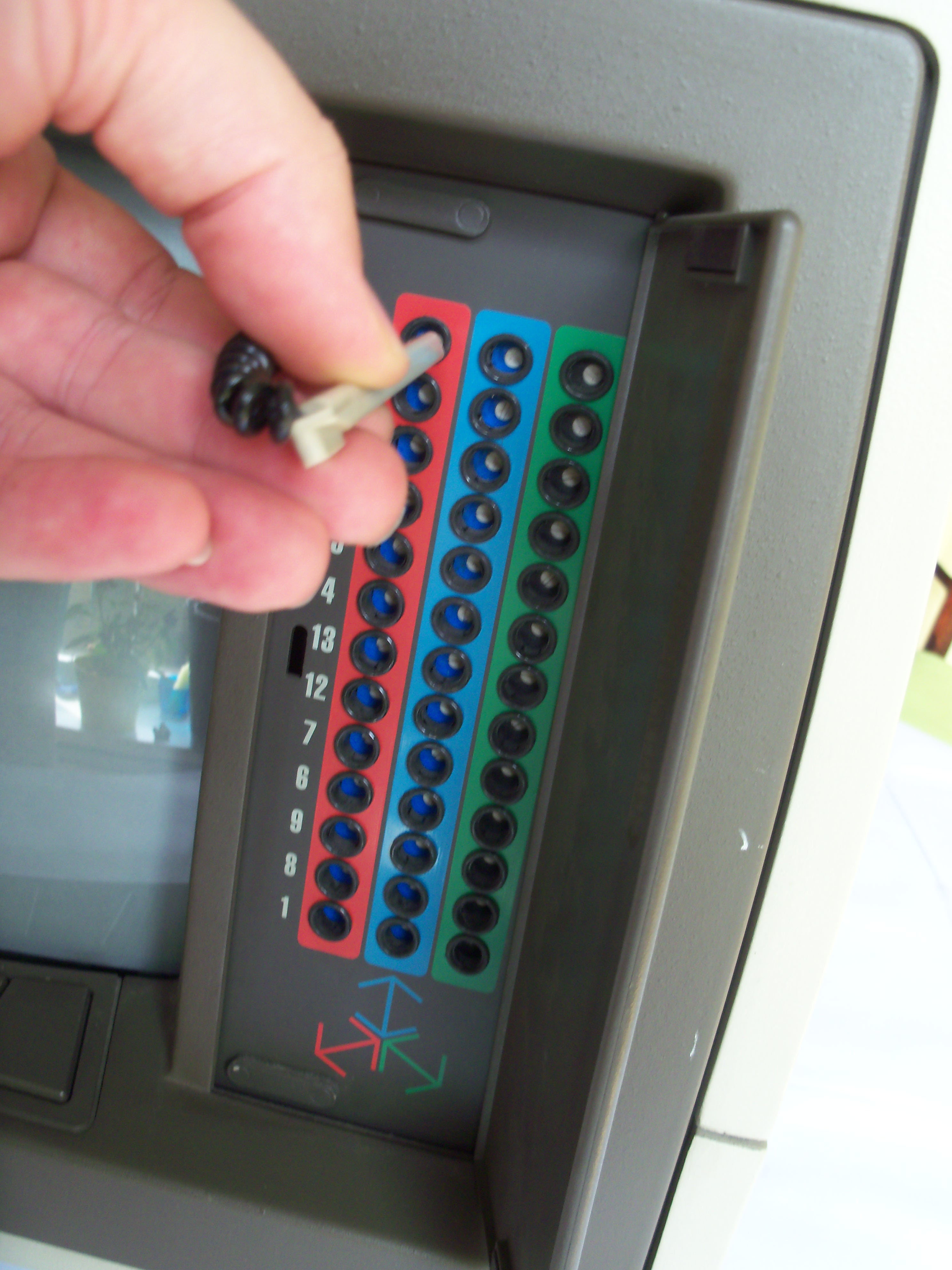 |
A tiny plastic screw driver (aligment tool) is attached to the case. See the HP 9845B/C Installation, Operation and Test Manual, page I-28 for the convergence alignment procedure. |
 |
The 98779A consists of the following main assembly groups:
|
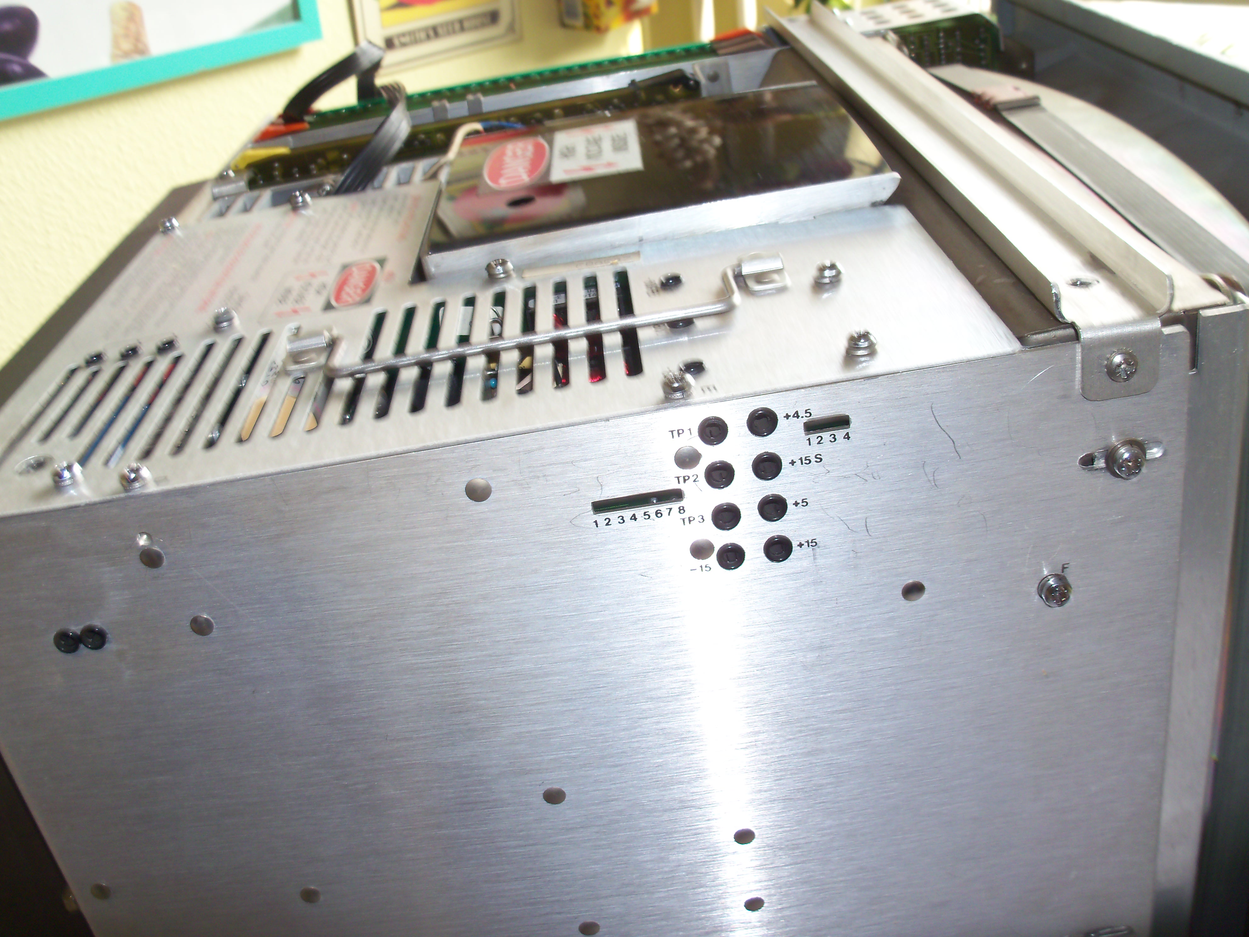 |
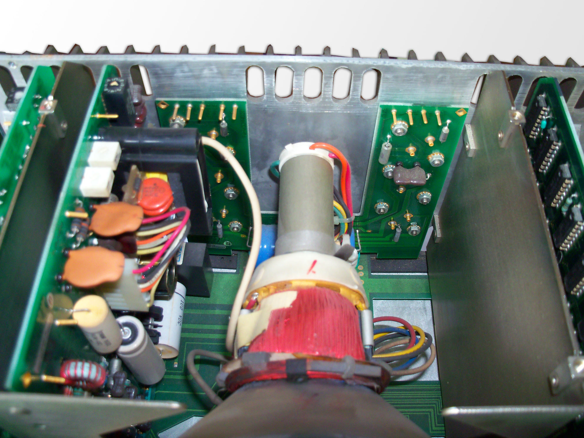
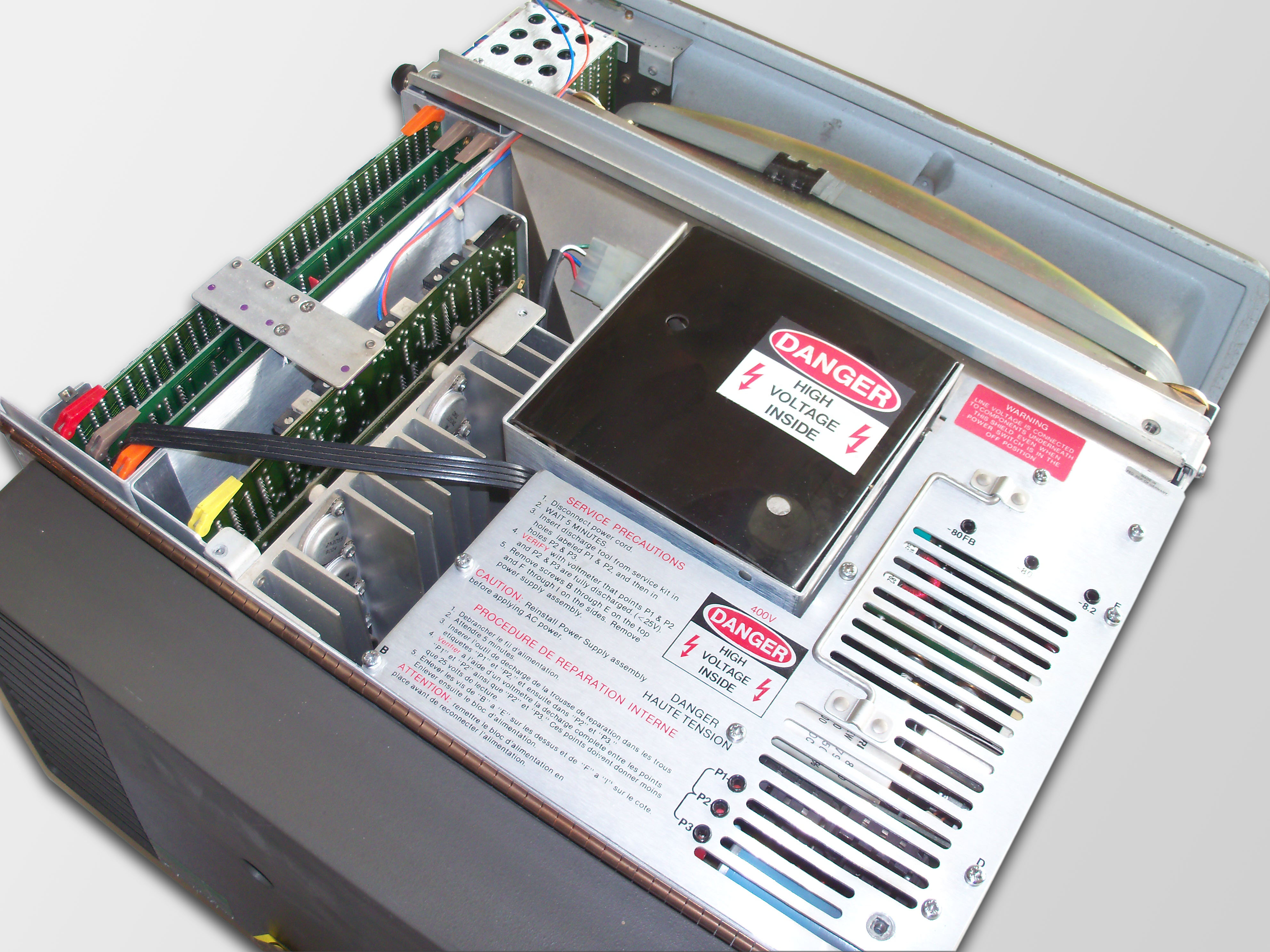
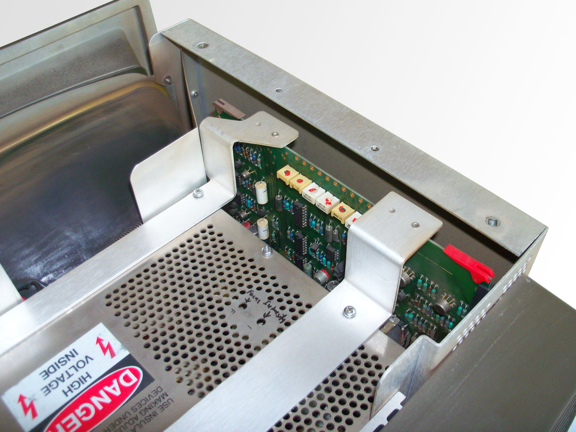
The power supply takes the most part of the 98770A volume. It is equipped with a couple of power good sensor circuits, which drive the diagnostic LEDs (see the 98770A service manual for meaning of the individual LEDs). Also there are test points for checking the most important voltages. The handle can be used to draw the PSU out of the casing. The PSU is connected to the 98770A motherboard by edge connectors at the bottom of the PSU. Be sure to remove the designated screws (leaving the others fastened) before lifting the PSU assemby. |
 |
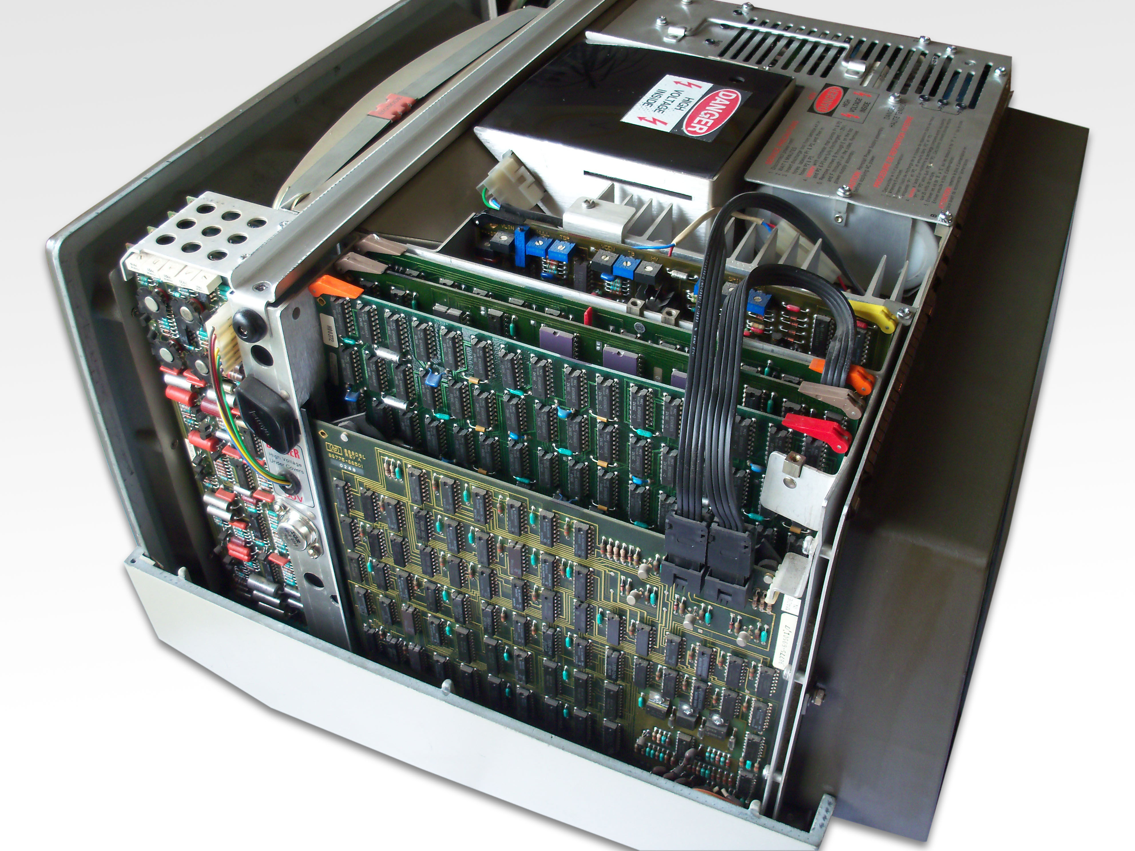
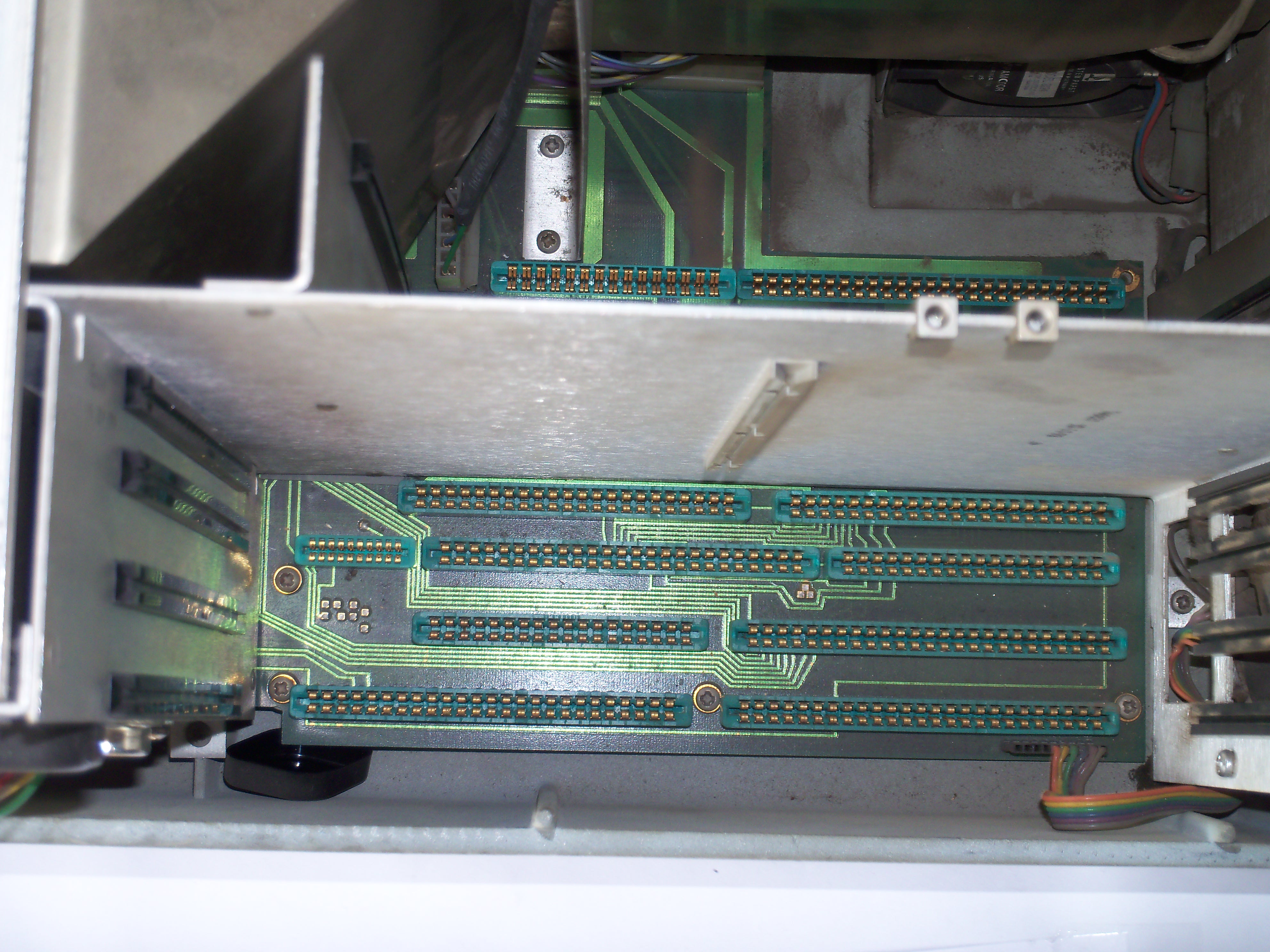
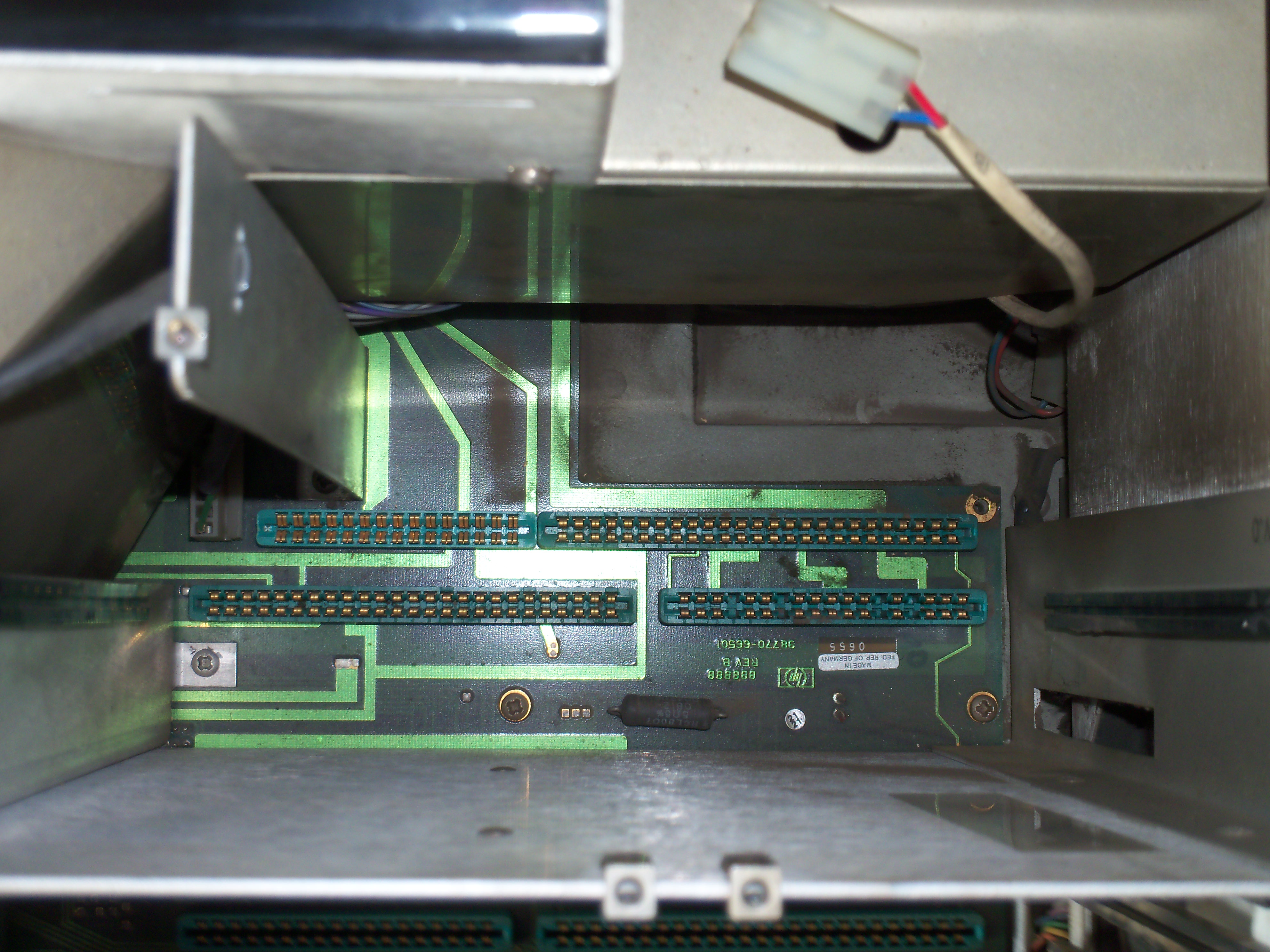
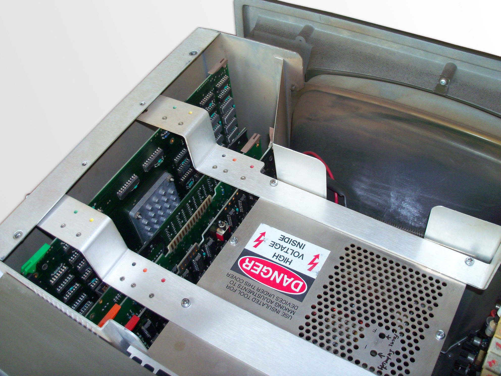
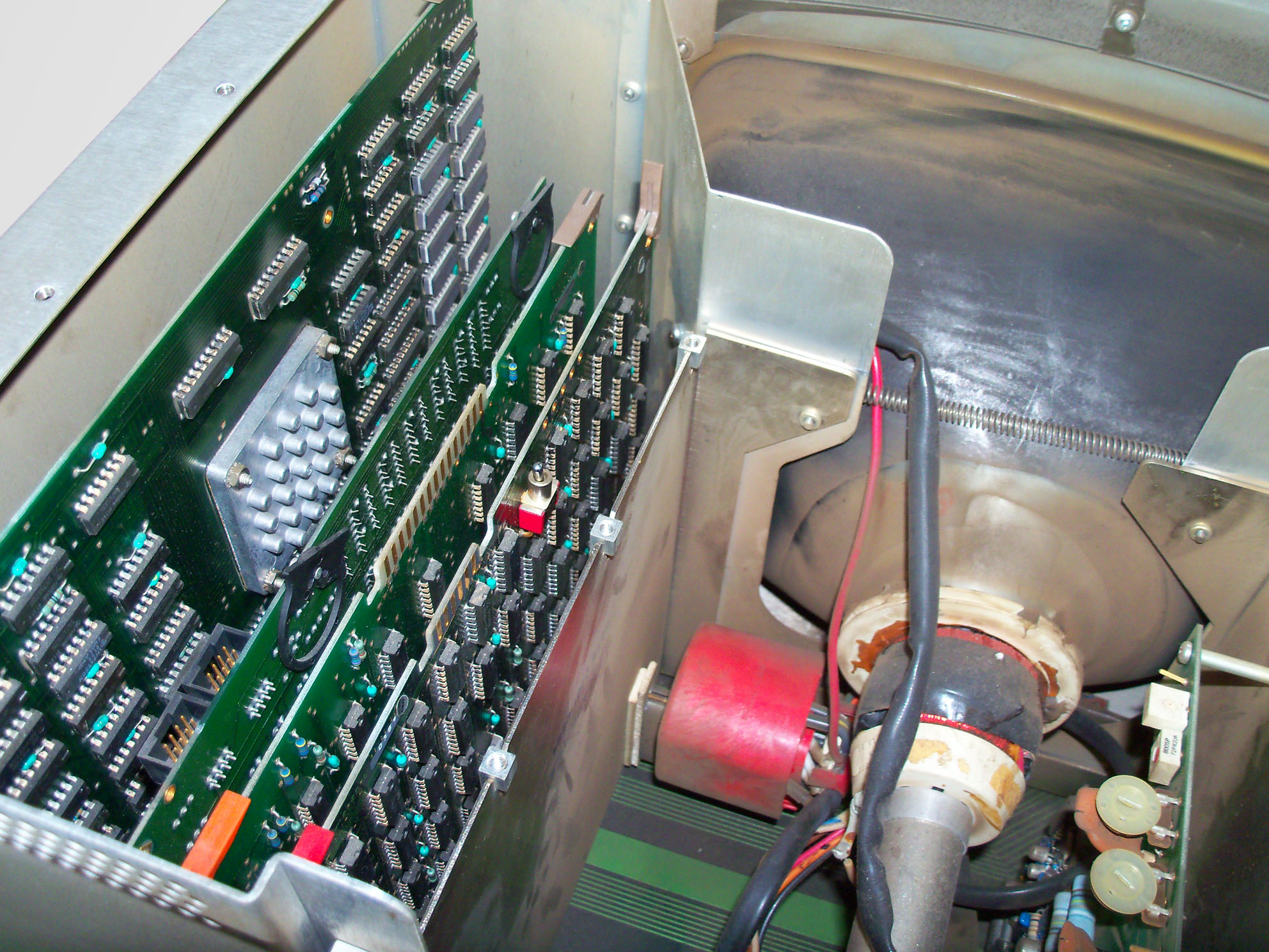
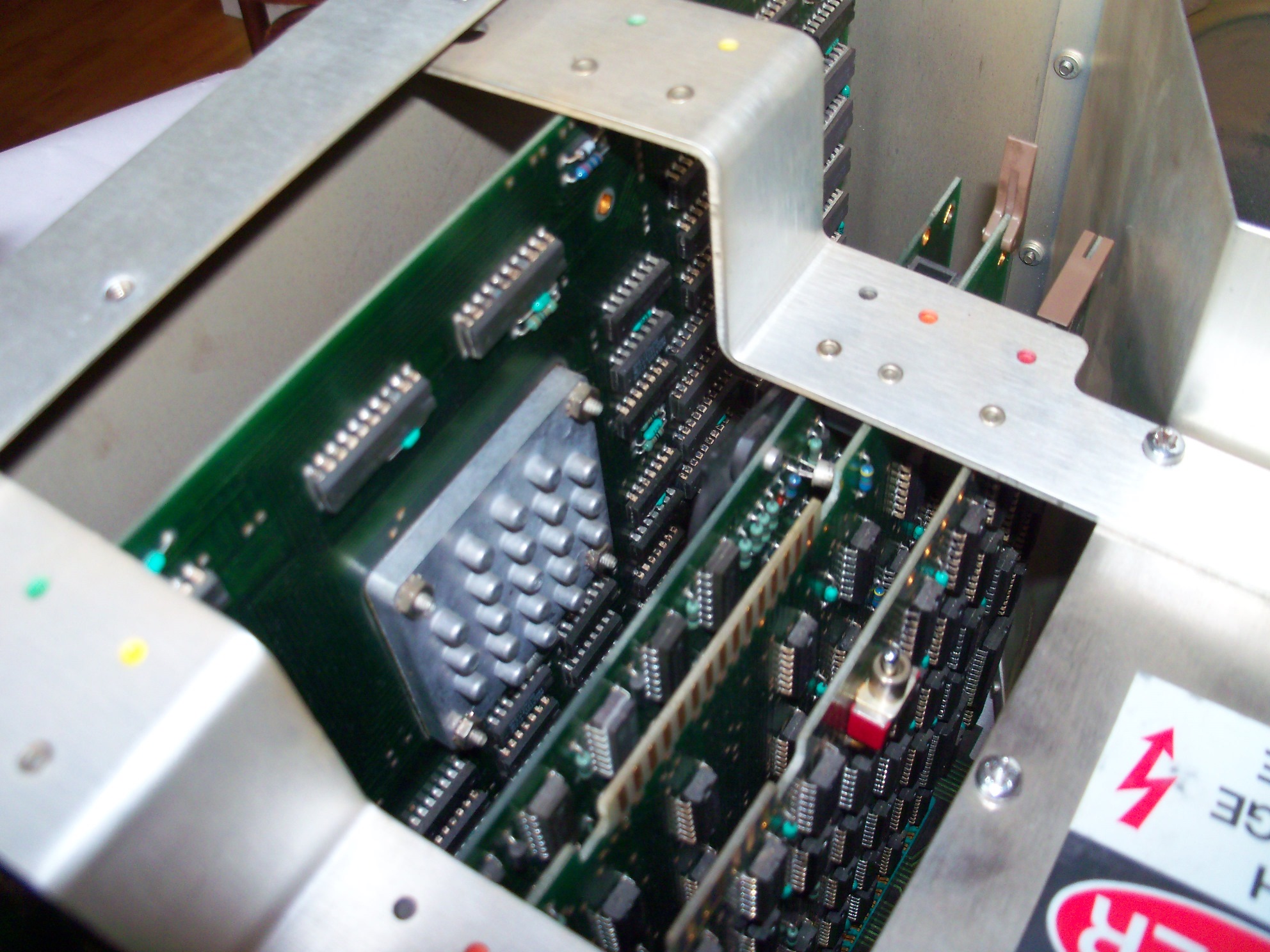
View from the top into the digital logic and analog circuit board cages. |
 |
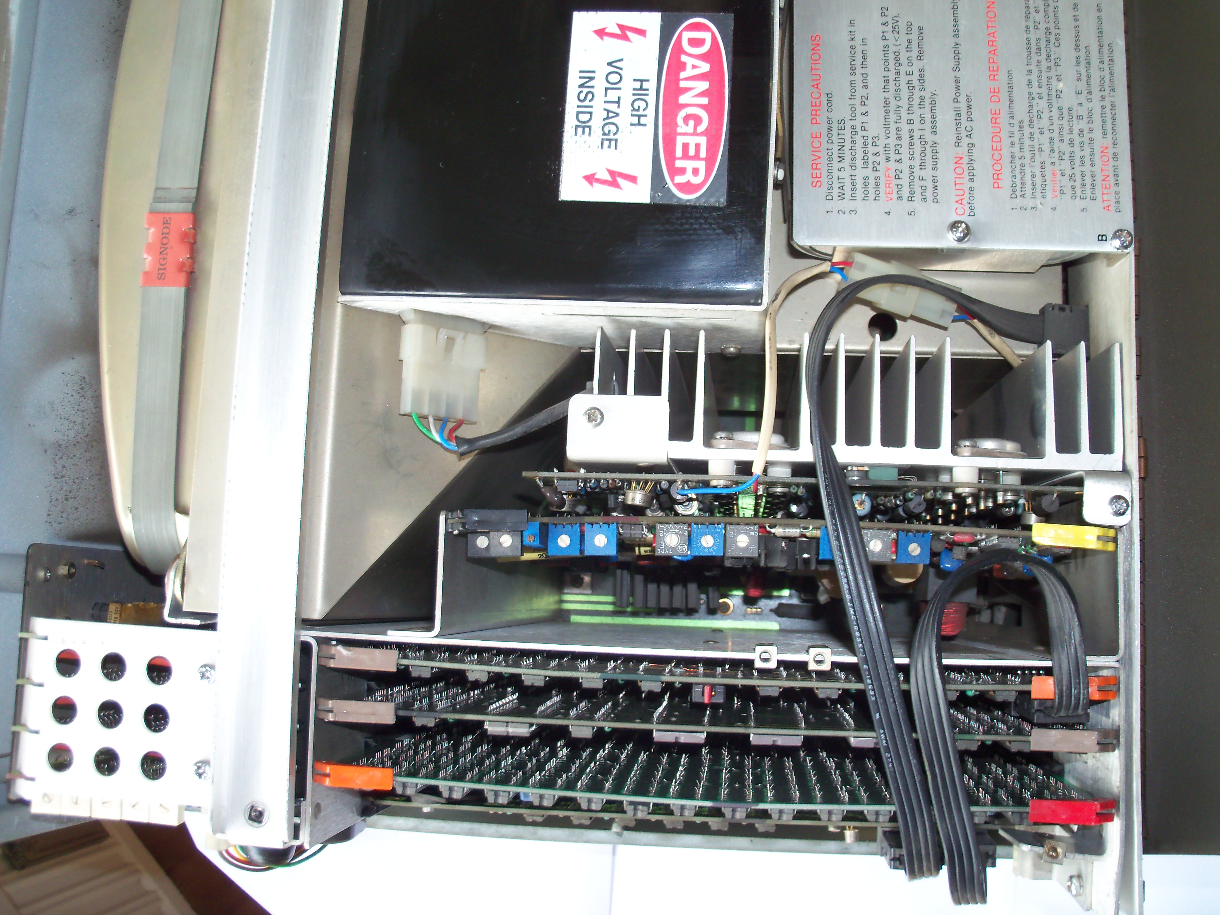
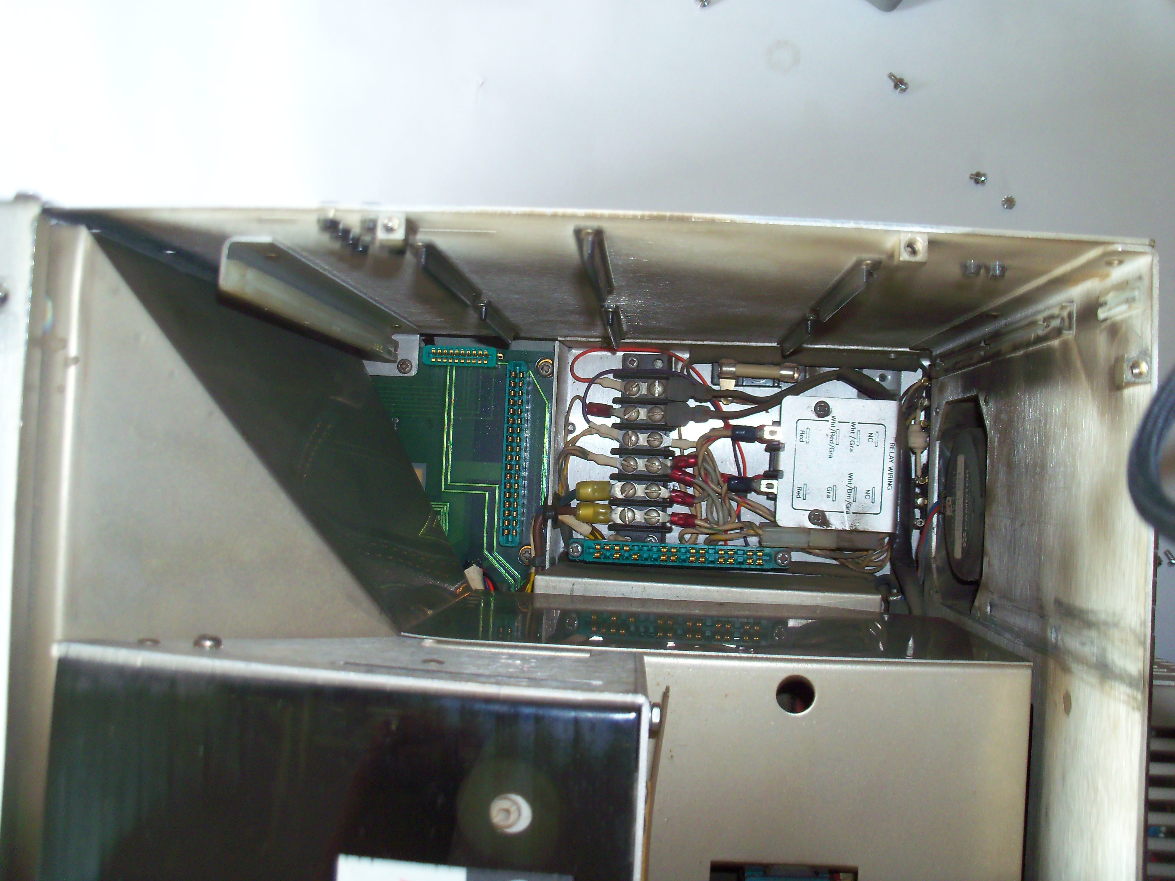
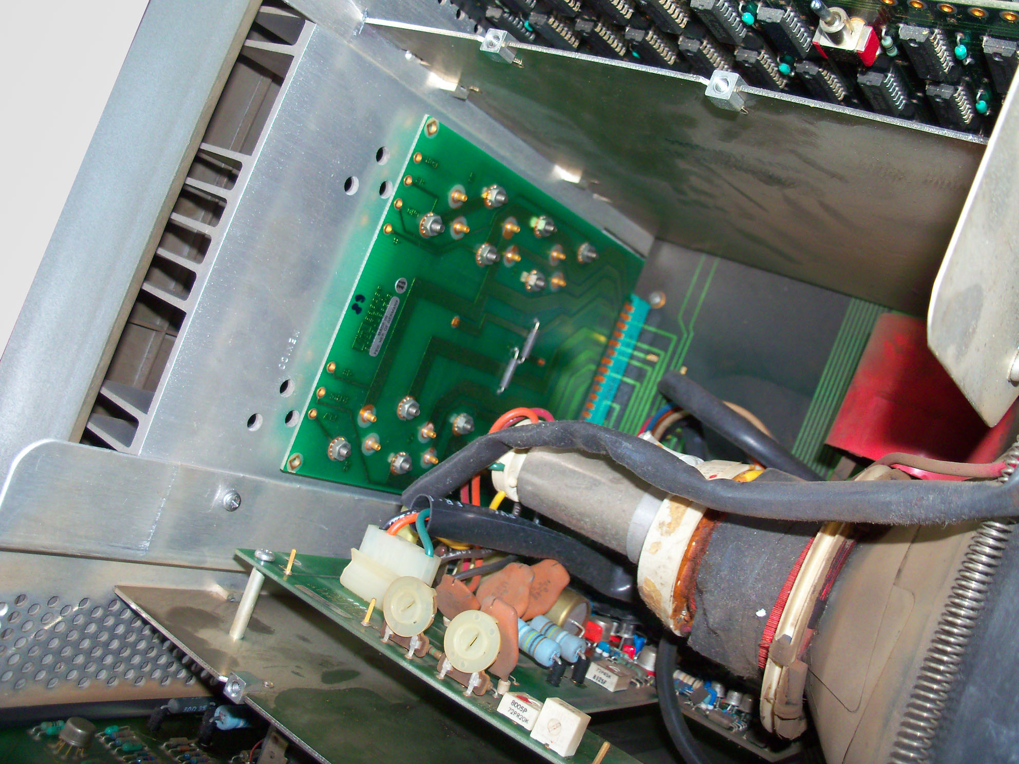
View from the right side of the monitor. See the lean convergence adjustment boards on the left, and the light pen controller board with the loop-through RGB signal cables. The light pen controller is controlled via the IOD bus.
|
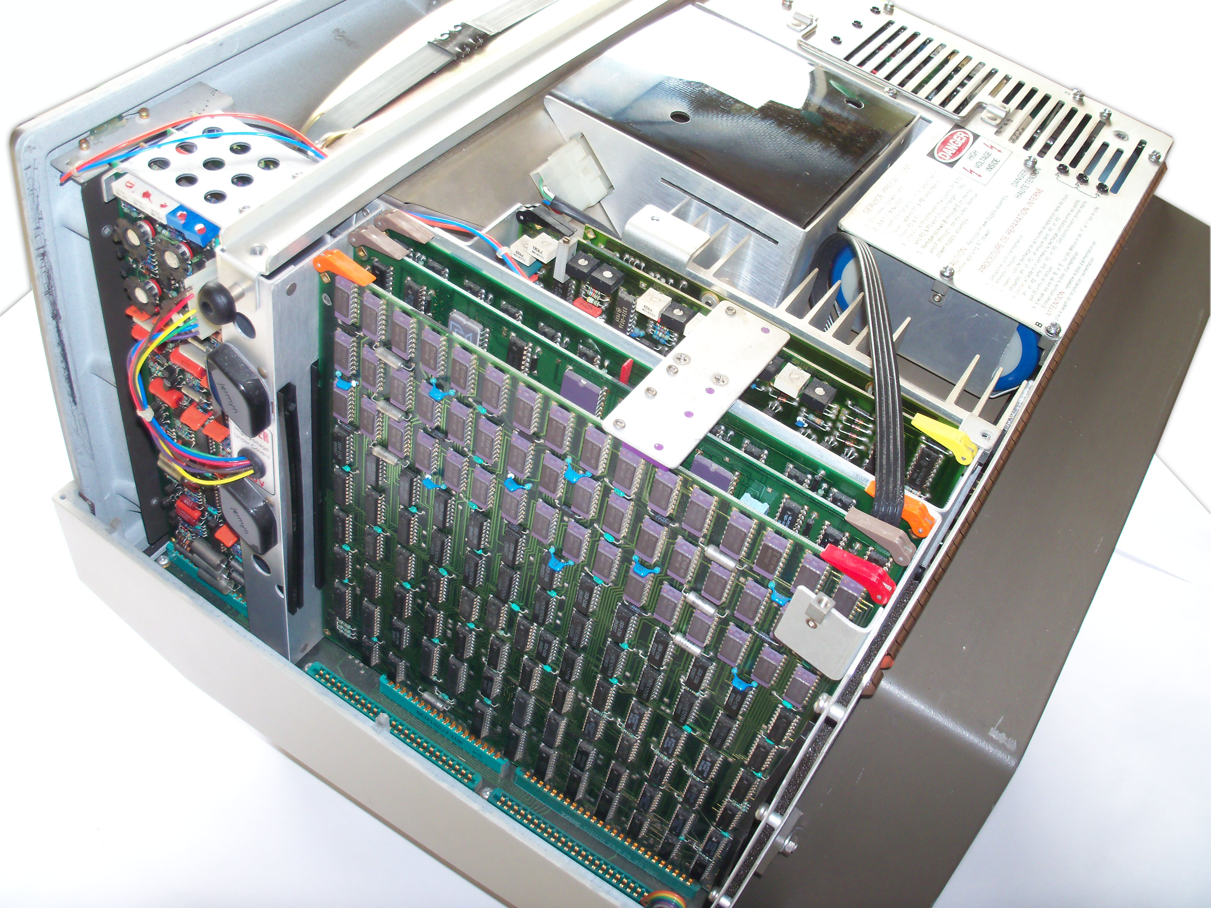 |
Behind the light pen controller is the assembly with the graphics memory. Further behind is the graphics controller board with the bit slice hardware graphics processor. |
 |
Two fans are mounted at the back of the 98770A for active cooling (500 watts power dissipation have to be exhausted out of the case). |
 |
Below the rear shielding is the control circuit for the three electron beams (targeted on the red, green and blue phosphor). The assembly also provides a test switch for displaying a full white alpha raster for geometry adjustments. |
 |
View into the digital logic board cage, with all boards removed. |
 |
View into the color convergence board cage, with the convergence adjustment boards removed. |
 |
View into the analog circuit board cage, with all boards removed. |
 |
View into the power supply cage with line filter (and early models with +/-15V fuses), with the PSU removed. |
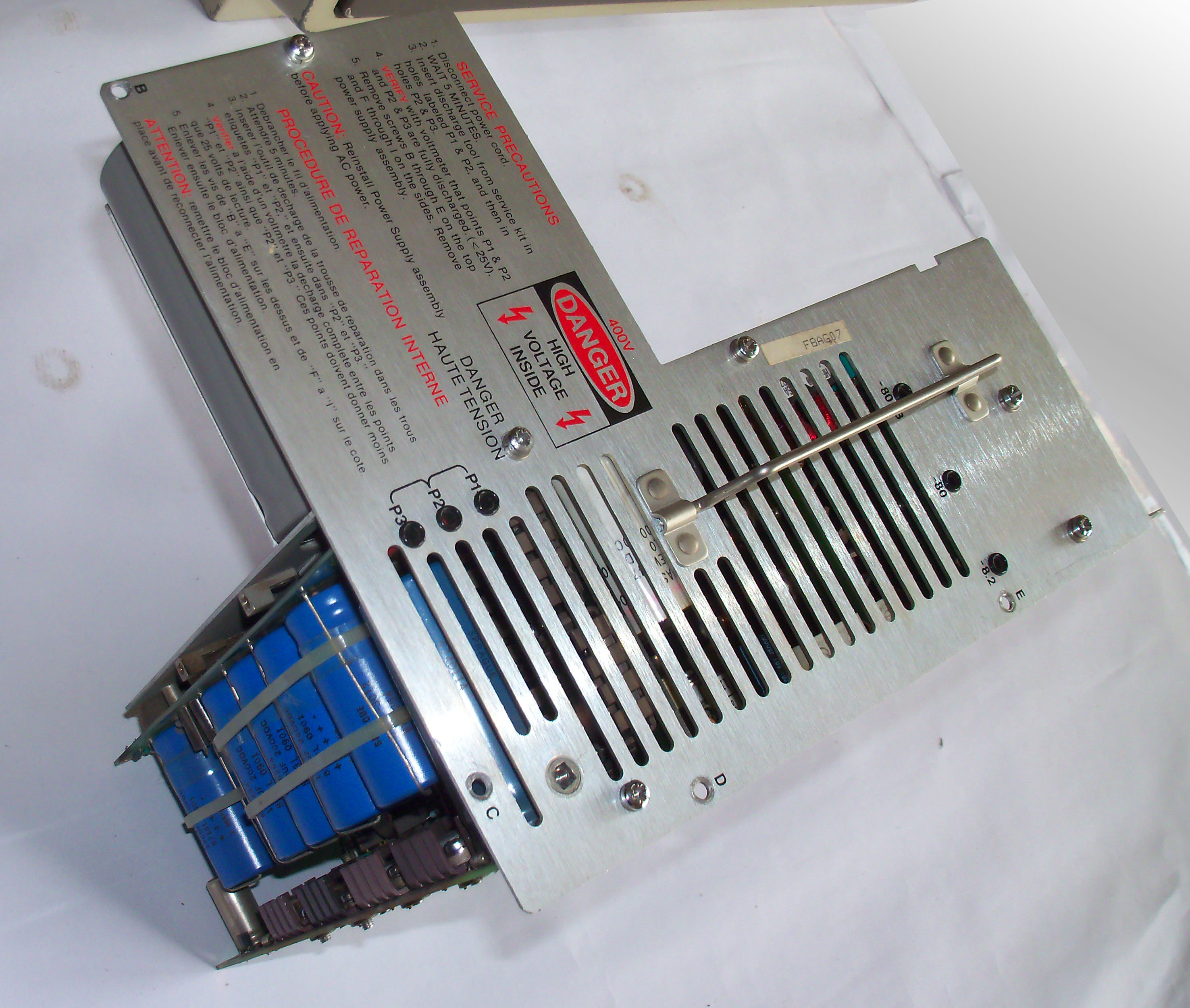 |
Power supply assembly group. All PSU boards are mounted to a aluminium plate. |
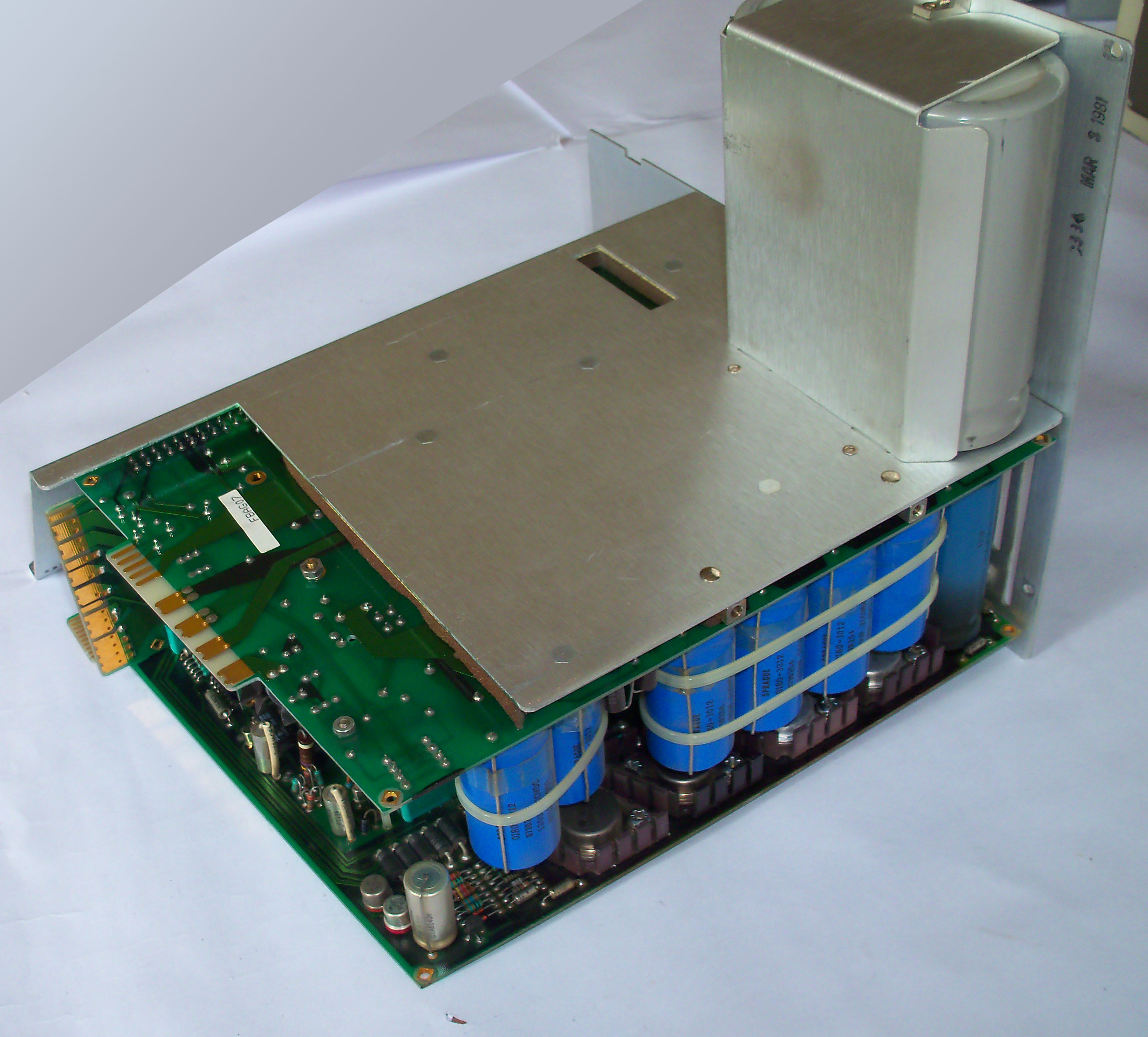 |
View of the PSU from another angle. See the large grey capacitors for leveling the input voltages. |
 |
Side view of the power supply unit. The whole assembly group consists of five single assemblies which are packed extremely close together. The PSU itself is a wonder of electronics, the most complex PSU I have ever seen, and is unfortunately a continuous headache because of the large number of components which may go defective. |
98780A Close Up
 |
The huge 98780A display is completely shielded below the plastic case. |
 |
The display has three areas with boards all secured by two hold-down straps:
|
 |
The sweep assembly with the display controls. |
 |
The high voltage driver board controls the CRT tube/yoke assembly. The driver regulators are soldered on a separate board and mounted on a heat sink at the back of the monitor. |
 |
View into the monitor with hold-down straps removed. From left to right:
|
 |
The graphics controller is equipped with a heat sink. Also note the test switch, which can be used to check the display logic and analog display circuits without display data from the mainframe. |
 |
The right compartment provides the space for the sweep assembly. |
 |
The left compartment holds all the digital logic (graphics controller, light pen controller, I/O logic and display logic). Note the small ribbon cable which connects the external light pen connector to the light pen logic. |
9835A Monitor Close Up
 |
The 9835A has a monitor attached, in contrast to the 9835B model, which uses a LED display built into the mainframe. The 9845A monitor looks very similar to the 98750A standard monitor of the 9845 models. In fact the housing is almost the same, the differences are below the hood. Also, the 9835 monitor uses another mechanism (ribbon cable with edge connector) for connection to the mainframe. |
 |
In contrast to the 98750A, the 9835A monitor does not show cooling fins on the back of the casing. Instead, there are two test buttons. The "A Test" button produces an inverse video raster, which checks about 80% of the displays circuits. The "D Test" button shows the installed characters set on the display. |
 |
With the cover removed, you get access to the CRT, the logic assemblies, and the analog circuits. |
 |
On the left side of the display you can identify the alpha control board. For the 9845, this part of the logic is installed in the mainframe. It connects to the I/O bus of the 9835A mainframe over the displays mother board and the ribbon cable. |
 |
On the other side of the 9835A display the display logic is installed, with the character generator, the feature & cursor generator and the timing generator. See the white ROM modules, which hold the character set. |
 |
Top view of the 9835A display. All assemblies are fixed with two bars. Below the aluminium shield is the high voltage cage. |
 |
See the 9835A display with bars and shield removed. Between the alpha control logic on the very left and the high voltage cage there is another board with the analog logic with the horizontal, vertical and video drivers. It provides a number of adjustments for display width and height. The high voltage circuit provide adjustments for intensity and focus. |
 |
View of the 9835A monitor with all boards removed. |
The RGB Interface
The original design of the 9845C did not include means for providing the CRT signal towards other monitor devices. The 9845C CRT monitor was mostly self-contained, it was built as an integrated unit of digital graphics hardware and analog CRT system in one single cabinet, so the interface between the 9845C mainframe and the 98770A color monitor is completely digital. The concept of connecting 'dumb' CRT systems with analog video signal input was not yet an option at the design time of the 98770A color monitor.
Jim Dunn from Dunn Instruments
with his 630 Film Recorder
However, because of the (at the time) tremendous graphics capabilities, there soon arose the need for high-quality hard copies and graphics display recording. One option was the 98777A camera attachment, especially in combination with large-format polaroid camera devices like the Dunn Instruments cameras (most of the screenshots available in HP's own publications were procuced in this way). Another alternative was to connect another high-resolution display via the HP-IB interface and to 'plot' the graphics on graphics CRT controllers like the 1350A Graphics Translator with vector display (see the Screen Arts section for the War Games movie, which was produced with this kind of technique).
With the 98776A RGB interface, HP obviously tried to address the need for delivering display information directly from the 98770A monitor to other raster display/recording devices simply as a standard analog RGB signal. Assuming you got the monitor with the right RGB and sync input, you can use this interface to connect a standard RGB monitor to the 9845C. Both the 98777A camera attachment and the 98776A RGB interface were introduced at the same time in 1981.
The principle for the 98776A RGB interface was quite simple. As the 98770A color monitor already had the necessary analog logic built into the cabinet, the required RGB signals were available as inverted TTL RGB signals anyway, so the signals just had to be diverged at the right points and inverted/normalized towards standard RGB levels. Also, the internal sync signals had to be ORed in order to derive the correct horizontal and vertical sync signals for RGB monitors.
The funny side is how this was achieved. It was real handwork. First, a small intermediate edge-connector PCB had to be installed in the light pen slot of the 98770A color monitor and connected to the internal 8-pole RGB cable in order to take off the necessary sync signals from the analog circuit board and the RGB signals from the RGB cable (this PCB also had a couple of active components and resistors for producing the standard RGB and sync signals). Then three plastic struts from the 98770A back cover had to be cut off and a rectangular hole was carved, in which another PCB with five BNC connectors was installed. The BNC PCB was then connected to the intermediate edge-connector PCB with a ten wire ribbon cable and the 98770A was readily equipped with a perfect RGB interface output.
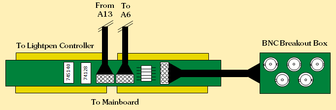
98776A RGB Interface
In order to use this RGB interface with a standard RGB monitor, the monitor has to support a non-interlaced bandwidth of at least 30 MHz (pixel clock is exactly 29.7984 MHz) and the following sync timings:
Vertical sync: 60 Hz with 550 µsec low during vertical blank every 16.7 msec
Horizontal sync: 29.1 kHz with 10.2 µsec low during horizontal blank every 34.4 µsec
In some cases where just the CRT analog amplifier logic (A6 assembly) or the CRT tube itself is defective and can't be repaired, the RGB interface - as it is quite easy to build - can be an alternative for providing a VGA output signal, which then can be displayed on a standard SVGA multisync monitor. Signal normalization is peformed with one 74S140 dual 4-input NAND line driver and one 74128 quad 2-input NOR line driver plus five resistors. If you exchange the three resistors used for the RED, GREEN and BLUE signals of the 98776A RGB interface (49 Ohms 1/8 Watts) with 470 Ohms you'll get the 0.7 Volts levels required by a standard VGA monitor (just for normalization of intensity, 49 Ohms would work, too). Sync signals are TTL anyway. If the circuit is placed directly by the monitor, impedance won't matter. Take into account that some VGA monitors expect +5V to be present at VGA pin 9 in order to detect the signal source.
Unfortunately, the RGB interface is no replacement for a completely defective 98770A monitor.
Thanks to François, the original schematics for the RGB interface are available, including a description on how to modify an existing 98770A color monitor. See the schematics section for download.